00191413-01.pdf - 第232页
7 Product / Adhesive Pa ttern User Manual Line Computer UNIX 7.1 Adhesive Pattern Editor Software Version 501.xx 01/99 Issue 7 - 2 7.1.2 Main Window of Adhesive Pattern Editor The areas of the mai n window and their fu n…
User Manual Line Computer UNIX 7 Product / Adhesive Pattern
Software Version 501.xx 01/99 Issue 7.1 Adhesive Pattern Editor
7 - 1
7 Product / Adhesive Pattern
7.1 Adhesive Pattern Editor
For the various package forms specific adhesive patterns (adhesive dot patterns) can be applied enabling the
components to be held (glued) securely on the PCB. The specific adhesive patterns for the various package
forms are defined with the aid of the Adhesive Pattern Editor.
7.1.1 Starting the Adhesive Pattern Editor
- In the "programming mode" the Adhesive Pattern Editor is activated by clicking on the Adhesive
Pattern icon on the desktop.
- If the LC program was installed for the "control mode", the Package Form Editor can be started via the
"PRODUCT" menu on the desktop.
● Click on the Adhesive Pattern icon on the desktop (or the "Adhesive Pattern Editor" option on
the "PRODUCT" menu).
The FSB containing the ".dm" file is opened. This file contains all already-defined adhesive
patterns.
● Select adhesive pattern file ".dm" by double-clicking.
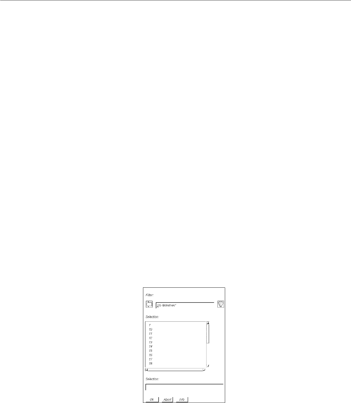
The following FSB containing the numbers of all previously defined adhesive patterns is displayed.
● Select adhesive pattern "xx" by double-clicking or enter new number on the keyboard and confirm
with OK. The main window containing the Adhesive Pattern Editor (see Fig. 7.1.1) is opened.
7 Product / Adhesive Pattern User Manual Line Computer UNIX
7.1 Adhesive Pattern Editor Software Version 501.xx 01/99 Issue
7 - 2
7.1.2 Main Window of Adhesive Pattern Editor
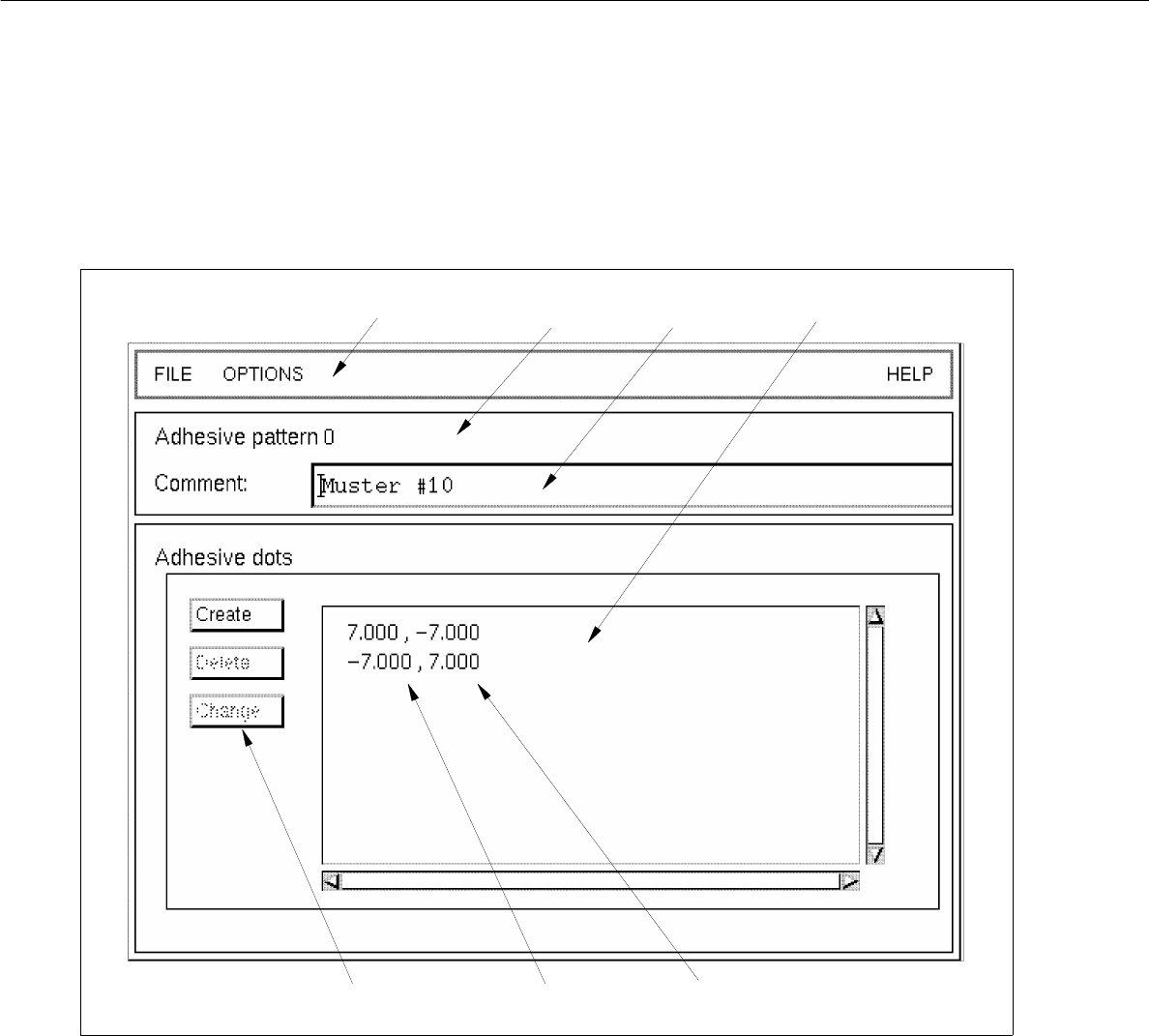
The areas of the main window and their functions are explained in the following.
Fig. 7.1.1 Main Window "Adhesive Pattern Editor"
The main window is subdivided as follows:
- Menu bar
- Title bar
- Editing field
- Command area
- Display area
menu bar title bar
editing field
x-coordinate
command area
display area
y-coordinate

User Manual Line Computer UNIX 7 Product / Adhesive Pattern
Software Version 501.xx 01/99 Issue 7.1 Adhesive Pattern Editor
7 - 3
Menu bar
The menu bar contains the "FILE", "OPTIONS" and "HELP" menus.
NOTE
Since the functions and operation of the menus are similar to those in other application programs of the line
computer, they are described comprehensively in chapt. 2.
Title bar
The title bar displays the number of the currently used adhesive pattern.
Editing field
An optional comment can be entered in the editing field below the title bar.
(Inverted commans and quotation marks are not accepted).
Command area (see section 7.1.2.1)
The adhesive dots forming the adhesive pattern can be created, deleted or changed by means of the
corresponding commands activated in this area.
Display area
The data of the x and y-coordinates of all created adhesive dots are displayed in the display area of the main
window.
7.1.2.1 Adhesive Pattern Editor Command Area
In the command area the adhesive dots of an adhesive pattern can be created, deleted or changed by means
of the corresponding commands.
COMMANDS
The procedures to be followed for the execution of the commands are described in the following.
- Creating
This command enables a new adhesive dot for the current adhesive pattern to be created.
● Click on Create in the command area of the main window of the "Adhesive Pattern Editor"
(see Fig. 7.1.1).
The window for entering the x/y-coordinates of the new adhesive dot is opened (see Fig. 7.1.2).