00191413-01.pdf - 第366页
12 Production Tools / Station and Line Confi guration User Manual Line Computer UNIX 12.1 Configuration Edit or Software Version 501.xx 01/99 Issue 12 - 4 12.1.2 Main Window of Configuration Editor (Structure Editor) In …
User Manual Line Computer UNIX 12 Production Tools / Station and Line Configuration
Software Version 501.xx 01/99 Issue 12.1 Configuration Editor
12 - 3
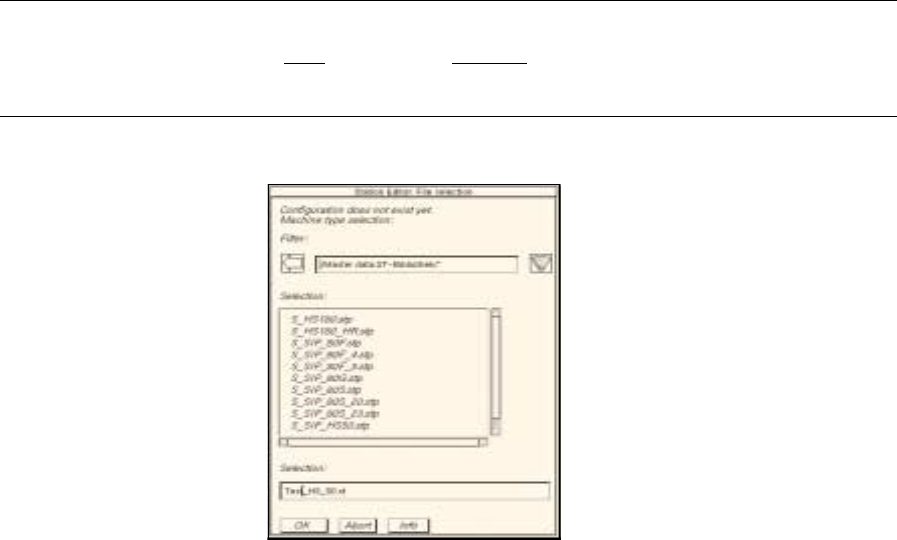
Generating a new configuration:
● Enter new station name "xx.st" and confirm with OK (or RETURN).
The FSB containing a listing of the machine types available for selection opens
(directory "master data:ST-Bibliothek").
NOTE
The station name may comprise max.
20 characters including the suffix ".st".
Some characters must not be used for the name, see chapt. 2, section 2.3 in this connection.
● Select machine type of the station entered and confirm with OK (or select machine type directly
by double-clicking).
The main window of the Configuration Editor, the Structure Editor is opened (see Fig. 12.1.1).
12 Production Tools / Station and Line Configuration User Manual Line Computer UNIX
12.1 Configuration Editor Software Version 501.xx 01/99 Issue
12 - 4
12.1.2 Main Window of Configuration Editor (Structure Editor)
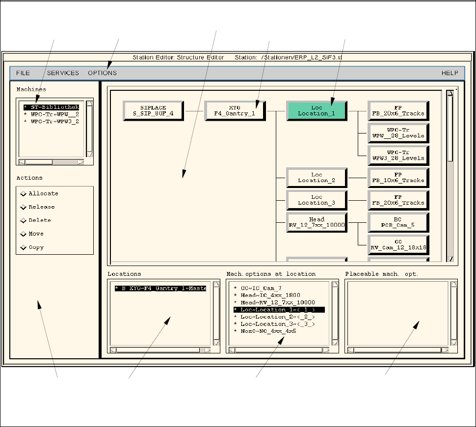
In the Structure Editor the maximum permitted configuration of the selected machine type is shown.
Fig. 12.1.1 Structure Editor (Machine Type "SIPLACE 80F)
menu bar
command area
selection field
"Locations"
selection field
"Mach. options at locat."
selection field
"Placeable mach. opt."
selection field
"Machines"
selected
machine option
location
display area

User Manual Line Computer UNIX 12 Production Tools / Station and Line Configuration
Software Version 501.xx 01/99 Issue 12.1 Configuration Editor
12 - 5
The main window is subdivided as follows:
- Display area (for description refer to section 12.1.2.1)
- Selection fields (for description refer to section 12.1.2.2)
- Menu bar The menu bar contains the "FILE", "SERVICES", "OPTIONS" and
"HELP" menus.
The "FILE" menu is described insection 12.1.2.3, the "SERVICES" menu
in section 12.1.2.4.
The "°Component changeover table" menu option of the "OPTIONS"
menu is described in section 12.1.2.5.
NOTE
Since the functions and operation of the "OPTIONS" and "HELP" menus are similar to those in other
application programs of the line computer, they are described comprehensively in chapt. 2.
- Command area (for description see section 12.1.2.6)
12.1.2.1 Display Area of Structure Editor
In the display area of the Structure Editor the maximum possible configuration of the machine type is displayed
as a structure.
- Each rectangle within the structure represents a machine option type.
- The machine option types are factory-defined. The original data of a machine option were defined in a
machine option type.
- A given machine option type can be the location for lower-level machine option types. These lower-
level machine option types are connected to the higher-level machine option type by means of lines.
- The topmost machine option type in the display area is the station. It is the location for lower-level
machine option types.
- Upon starting the Structure Editor the rectangle of the topmost machine option type is selected.
If another rectangle is clicked on, the displays in the selection fields change (see section 12.1.2.2).
- By double-clicking on the rectangle of a machine option type, the same becomes a machine option,
which is, however, not part of the machine yet.
12.1.2.2 Selection Fields of Structure Editor
For the machine options of a location to be displayed in the appropriate selection field, the location
(rectangle) must first be selected in the display area by clicking the mouse button.
Selection Fields "Locations", "Mach. options at locat.", "Placeable mach. opt.":
These three selection fields are located in the main window of the Structure Editor (see Fig. 12.1.1) below the
display area. They are used for the selection of machine option s on which actions such as allocating, releasing,
deleting, moving or copying are to be performed (see section 12.1.2.6).