00191413-01.pdf - 第107页
User Manual Line Computer UNIX 3 Desktop (Root Window) Software Version 501.xx 01/99 Issue 3.2 Desktop User Interface 3 - 37 - Ico n Errors = Error Signall ing Sys tem User Int erface ( see cha pt. 15) The error messag e…

3 Desktop (Root Window) User Manual Line Computer UNIX
3.2 Desktop User Interface Software Version 501.xx 01/99 Issue
3 - 36
NOTE
Since the meaning and functions of the applications (icons) contained in the "Product" and "Production Tools"
main groups are identical to the applications (menu options) of the "PRODUCT" and "PRODUCTION TOOLS"
menus, they were already briefly described in section 3.2.1.4 and section 3.2.1.5.
The name of an icon sometimes differs from the item on the menu having the same meaning and function
(e.g. icon "Component" -> menu item "Component Editor", icon "Package Form" -> menu item "Package Form
Editor", etc.).
A detailed description on the individual application programs is contained in the related chapters.
3.2.2.1 "Control" Group
The basic function of the line computer control system is to distribute jobs from the user or a higher-level CAX
system to the individual stations of the line. The control system organizes the data supply to the stations
throughout the line so that the jobs can be processed. Each job comprises a number of PCBs (lot).
- Icon Job = Job Control User Interface (see chapt. 14)
The user interface of Job Control allows the user to insert and edit jobs.
Job Control generates a job list. This list is stored in the job file and is managed by Job Control.
A check takes place in Job Control as to whether the product data required for a particular job are
available and whether the specific job can be executed on the line by means of the current set-up.
When all requirements have been met, the job can be passed to the Station Controller. Completed
jobs are passed back to Job Control.
- Icon Set-up modification = Set-up Modification User Interface (see chapt. 14)
With the aid of the user interface of the Set-up Modification Generator the user can have different
types of the set-up of each selected station displayed and activate the creation of set-up changeover
instructions via the Set-up Modification Generator. The set-ups and changeover instructions are dis-
played on the user interface of the Set-up Modification Generator and can be output on a connected
printer.
- Icon MaDaMaS = MaDaMaS - User Interface (see chapt. 16)
The
MaDaMaS
(Machine Data Management System) collects all data of a line and displays them
graphically via the user interface. It is thus possible for the user to obtain, at any time, an updated
status display of either an entire line or individual stations. This allows appropriate corrective actions
to be taken in the case of malfunctions, errors or work load imbalances.
User Manual Line Computer UNIX 3 Desktop (Root Window)
Software Version 501.xx 01/99 Issue 3.2 Desktop User Interface
3 - 37
- Icon Errors = Error Signalling System User Interface (see chapt. 15)
The error messages are classified into informative messages for the observation of the system, error
messages not entailing any danger for the overall system, and warning messages. Depending on the
individual requirements of the user, he can select from the different message types the message he
needs and can have this message displayed on the user interface of the error signalling system.
3.2.3 Line Selection Button and Display Area
3.2.3.1 Line Selection Button
Above the view area the line selection button is located indicating the designation of the current line (see Fig.
3.1.1). If the button is clicked on, a new line can be selected, provided several lines were configured upon
installation
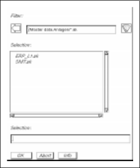
- Selection of a new line
● Click on the Line Selection button.
The FSB for the selection of a new line (see example below) is opened.
● Select <Name>.ak of the desired line by double-clicking.
The FSB is closed. The most recently displayed line is deleted from the display area, and the
stations of the newly selected line are displayed symbolically in the display area after a few
moments.

3 Desktop (Root Window) User Manual Line Computer UNIX
3.2 Desktop User Interface Software Version 501.xx 01/99 Issue
3 - 38
3.2.3.2 View Area
Here, all stations that were entered for a line during the line configuration (see chapt. 12, section 12.2) are
represented by type-specific icons. Every station symbol is identified by the name that was entered for the
respective station during station configuration (see chapt. 12, section 12.1). As a rule, the currently used line
is displayed. Each station represented in the display area is provided with
sensitive
areas (see Fig. 3.1.2).
These areas have been assigned functions which can be activated by clicking the mouse.
- Feeder Part
If an area of a station is clicked on that represents a given feeder part of that station (see Fig. 3.1.2), first
an FSB containing the names of all already-defined set-ups is opened. After selecting or entering a set-
up name, the user interface of the Set-Up Editor for the respective station, containing the display of the
selected feeder part, is opened (see chapt. 13).
The set-up of a station can be described by means of the Set-Up Editor.
- i Symbol
Clicking on the area of a station containing the "i" symbol (see Fig. 3.1.2) causes the user interface of
the respective station controller to be opened (see chapt. 14).
The user is provided with the possibility to inform himself of the state of a given station via the
respective station controller. Information about the operating mode, the current lot and the current
PCB, the station configuration and station messages is displayed.
- Bar Chart Symbol
If the area containing the bar chart symbol is clicked on at a station (see Fig. 3.1.2), the MaDaMaS
evaluation screen opens (see chapt. 16).
In the case of an adhesive application station, the "Distribution of events" evaluation type is displayed,
in the case of a placement station, the "Track information" evaluation type.
3.2.4 Main Menu
The main menu is opened by clicking on the right border of the screen holding down the left mouse button.
For structure and operation of the main menu refer to chapt. 2 of this manual.
NOTE
The main menu is only used for special procedures in the event of problems in the LC program, following
any changes made to system settings, and for the
Shut Down
process of the computer system!