00191413-01.pdf - 第200页
6 Product / Package Form User Manu al Line Computer UNIX 6.1 Package Form Editor Software Version 501.xx 01/99 Issue 6 - 22 - SST number "11" Flip-chip camera SIPLACE 80F3/F 4 Componen t dimen sion 20 x 20 mm C…

User Manual Line Computer UNIX 6 Product / Package Form
Software Version 501.xx 01/99 Issue 6.1 Package Form Editor
6 - 21
General data on the sensor system types (SST) available
-
SST number "2"
Component camera HS-180
Component dimension (small contact area) 43 x 43 mm
Component dimension (large contact area) 50 x 50 mm
Camera’s field of view 35 x 35 mm
Resolution 74
µ
m/pixel
Minimum pin pitch 0.4 mm
-
SST number "3"
Coplanarity Module HS-180
-
SST number "6"
RV camera SIPLACE 80S-15/F3
Component dimension 14 x 14 mm
Camera’s field of view 18 x 18 mm
Resolution 54
µ
m/pixel
Minimum pin pitch 0,5 mm
Camera illumination 2 programmable illumination levels
-
SST number "7"
IC camera SIPLACE 80F3/F
4
Component dimension 55 x 55 mm
Camera’s field of view 38 x 38 mm
Resolution 74
µ
m/pixel
Minimum pin pitch 0,4 mm
Camera illumination 3 programmable illumination levels
-
SST number "8"
Coplanarity Module SIPLACE 80F3/F
4
-
SST number "9"
RV camera SIPLACE 80S-15/F3
Component dimension 14 x 18 mm
Camera’s field of view 19 x 25 mm
Resolution 54
µ
m/pixel
Minimum pin pitch 0,5 mm
Camera illumination 2 programmable illumination levels
-
SST number "10"
IC camera Fine Pitch SIPLACE 80F3/F
4
Component dimension 38 x 38 mm
Camera’s field of view 26,4 x 26,4 mm
Resolution 55
µ
m/pixel
Minimum pin pitch 0,3 mm
Camera illumination 3 programmable illumination levels

6 Product / Package Form User Manual Line Computer UNIX
6.1 Package Form Editor Software Version 501.xx 01/99 Issue
6 - 22
-
SST number "11"
Flip-chip camera SIPLACE 80F3/F
4
Component dimension 20 x 20 mm
Camera’s field of view 12,2 x 9,2 mm
Resolution 20
µ
m/pixel
Minimum pin pitch 0,2 mm
Minimum ball radius of BGA’s 0,04 mm
Camera illumination 3 programmable illumination levels
-
SST number "12"
RV camera (12-nozzle head) SIPLACE 80S-20/23/HS-50/F
4
Component dimension 18 x 18 mm
Camera’s field of view 24 x 24 mm
Resolution 50
µ
m/pixel
Minimum pin pitch 0,5 mm
Minimum ball radius of BGA’s 0,2 - 0,25 mm
Camera illumination 3 programmable illumination levels
-
SST number "13"
RV camera (6-nozzle head) SIPLACE 80F
4
Component dimension 32 x 32 mm
Camera’s field of view 39 x 39 mm
Resolution 81
µ
m/pixel
Minimum pin pitch 0,5 mm
Minimum ball radius of BGA’s ca. 200
µ
m
Camera illumination 2 programmable illumination levels
-
SST number "14"
Flip Chip camera (6-nozzle head) SIPLACE 80F
5
Component dimension 15 x 15 mm
Camera’s field of view 19,2 x 19,2 mm
Resolution 40
µ
m/pixel
Minimum pin pitch 0,5 mm
Minimum ball radius of BGA’s 0,2 - 0,25 mm
Camera illumination 3 programmable illumination levels
-
SST number "17"
Coplanarity Module SIPLACE 80F
5
User Manual Line Computer UNIX 6 Product / Package Form
Software Version 501.xx 01/99 Issue 6.1 Package Form Editor
6 - 23
6.1.2.8 View Area - "Handling Data" Screen
-
If the "Sensor type" button is activated in the command area, all created sensor system types are shown in
the view area (see Fig. 6.1.5).
-
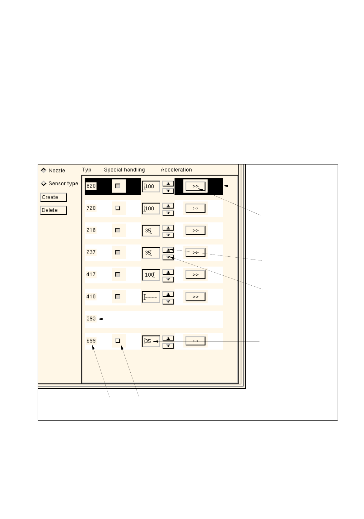
If the "Nozzle" button is activated in the command area, the numbers of all nozzles created as well as the
acceleration selected in each case are displayed in % (see Fig. 6.1.9).
Each nozzle (except for nozzles of the 3xx type) is assigned its own buttons by means of which the
settings for the "Acceleration" special handling option can be selected (see section 6.1.2.9).
Layout of the View Area for the "Nozzle" Setting
Abb. 6.1.9 View Area - "Nozzle" Setting
Button ">>"
Button for
Selected
nozzle
Arrow button
Arrow button
(to increase the
(to reduce the
Nozzle
Editing/display box
(opens the dialog box
for axis-specific settings)
acceleration value)
acceleration value)
Special handling not
possible for this nozzle
acceleration value [%]
special handling "Acceleration"number
type