00191413-01.pdf - 第236页
7 Product / Adhesive Pa ttern User Manual Line Computer UNIX 7.1 Adhesive Pattern Editor Software Version 501.xx 01/99 Issue 7 - 6
User Manual Line Computer UNIX 7 Product / Adhesive Pattern
Software Version 501.xx 01/99 Issue 7.1 Adhesive Pattern Editor
7 - 5
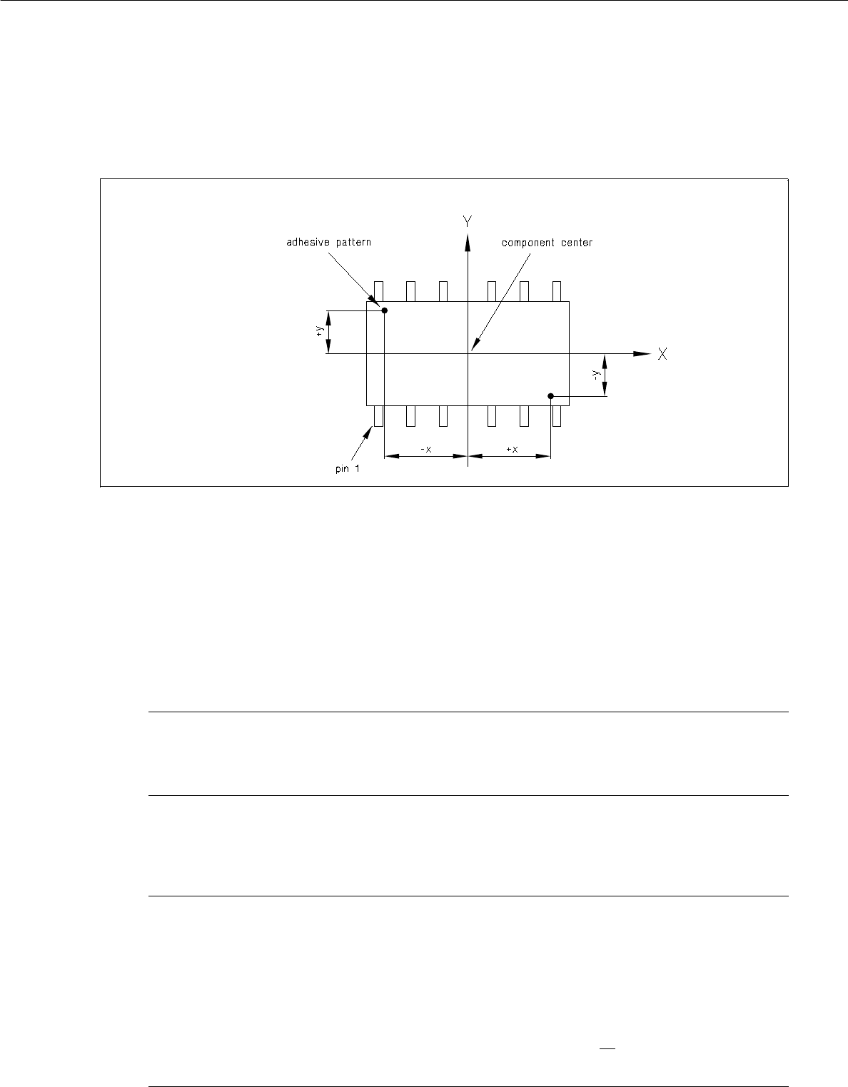
7.1.2.2 Definition of x/y-Coordinates for Adhesive Dots
Fig. 7.1.3 Definition of x/y-coordinates for adhesive dots
Editing a new adhesive dot
● Click on Create in the command area of the main window "Adhesive Pattern Editor" (see Fig. 7.1.1).
The window for editing the coordinate data of the new adhesive dot is opened (see Fig. 7.1.2).
● Click on editing field "X" and enter value for the x-coordinate (observe correct sign).
● Click on editing field "Y" and enter value for the y-coordinate (observe correct sign).
NOTE
In order to be able to apply the adhesive dots of an adhesive pattern by means of an adhesive
dispensing cartridge, a minimum spacing of the adhesive dots must be observed.
● Confirm the entries with OK.
The window is closed. The coordinate data of the created adhesive dot are displayed in the main
window "Adhesive Pattern Editor".
NOTE
If invalid values or characters (e.g. a comma as decimal point) were entered or if the minimum
distance between adhesive dots in an adhesive pattern has not been observed, a dialog box contai-
ning a corresponding error message is displayed. The fields containing the invalid values are sur-
rounded by a red frame. The dialog box must first be acknowledged by selecting OK. Thereafter, the
entries can be corrected and confirmed with OK.
The edited values are retained when the window is closed. If, however, no
saving operation is carried
out upon exiting the Adhesive Pattern Editor, the edited data will be lost.

7 Product / Adhesive Pattern User Manual Line Computer UNIX
7.1 Adhesive Pattern Editor Software Version 501.xx 01/99 Issue
7 - 6

User Manual Line Computer UNIX
Software Version 501.xx 01/99 Issue
8 - I
Contents
Page
Product / PCB
8.1 PCB Editor. . . . . . . . . . . . . . . . . . . . . . . . . . . . . . . . . . . . . . . . . . . . . . . . . . . . . . . . . . . . . . . 8 - 1
8.1.1 Description of a PCB . . . . . . . . . . . . . . . . . . . . . . . . . . . . . . . . . . . . . . . . . . . . . . . . . . . . . . . 8 - 2
8.1.1.1 PCB Data . . . . . . . . . . . . . . . . . . . . . . . . . . . . . . . . . . . . . . . . . . . . . . . . . . . . . . . . . . . . . . . . 8 - 2
8.1.1.2 PCB Source Data. . . . . . . . . . . . . . . . . . . . . . . . . . . . . . . . . . . . . . . . . . . . . . . . . . . . . . . . . . 8 - 2
8.1.1.3 PCB Structure. . . . . . . . . . . . . . . . . . . . . . . . . . . . . . . . . . . . . . . . . . . . . . . . . . . . . . . . . . . . . 8 - 3
8.1.1.4 PCB Coordinate System. . . . . . . . . . . . . . . . . . . . . . . . . . . . . . . . . . . . . . . . . . . . . . . . . . . . .8 - 4
8.1.2 Starting the PCB Editor . . . . . . . . . . . . . . . . . . . . . . . . . . . . . . . . . . . . . . . . . . . . . . . . . . . . . 8 - 6
8.1.3 Main Display Window of Structure Editor. . . . . . . . . . . . . . . . . . . . . . . . . . . . . . . . . . . . . . . . 8 - 7
8.1.3.1 FILE Menu . . . . . . . . . . . . . . . . . . . . . . . . . . . . . . . . . . . . . . . . . . . . . . . . . . . . . . . . . . . . . . .8 - 9
8.1.3.2 SERVICES Menu . . . . . . . . . . . . . . . . . . . . . . . . . . . . . . . . . . . . . . . . . . . . . . . . . . . . . . . . . 8 - 10
8.1.3.3 Command Area of the Structure Editor (Structure Mode) . . . . . . . . . . . . . . . . . . . . . . . . . . 8 - 10
8.1.3.4 Setting Area of Structure Editor (Graphic Mode) . . . . . . . . . . . . . . . . . . . . . . . . . . . . . . . . . 8 - 16
8.1.3.5 Display of the Cluster Data in the Structure Editor (Graphic Mode). . . . . . . . . . . . . . . . . . . 8 - 20
8.1.3.6 Display of PP-Data in the Structure Editor (Graphic Mode) . . . . . . . . . . . . . . . . . . . . . . . . . 8 - 21
8.1.3.7 Colors and Their Meanings in the Structure Editor (Graphic Mode). . . . . . . . . . . . . . . . . . . 8 - 22
8.1.3.8 Symbols and Their Meanings in the Structure Editor (Graphic Mode). . . . . . . . . . . . . . . . . 8 - 23
8.1.4 Cluster Editor Window . . . . . . . . . . . . . . . . . . . . . . . . . . . . . . . . . . . . . . . . . . . . . . . . . . . . . 8 - 25
8.1.4.1 EDIT Menu . . . . . . . . . . . . . . . . . . . . . . . . . . . . . . . . . . . . . . . . . . . . . . . . . . . . . . . . . . . . . . 8 - 27
8.1.4.2 SERVICES Menu . . . . . . . . . . . . . . . . . . . . . . . . . . . . . . . . . . . . . . . . . . . . . . . . . . . . . . . . . 8 - 28
8.1.4.3 Editing Area of Cluster Editor . . . . . . . . . . . . . . . . . . . . . . . . . . . . . . . . . . . . . . . . . . . . . . . . 8 - 28
8.1.4.4 Setting Area Cluster Editor. . . . . . . . . . . . . . . . . . . . . . . . . . . . . . . . . . . . . . . . . . . . . . . . . . 8 - 29
8.1.5 Fiducial Editor Window. . . . . . . . . . . . . . . . . . . . . . . . . . . . . . . . . . . . . . . . . . . . . . . . . . . . . 8 - 30
8.1.5.1 Editing Area of the Fiducial Editor . . . . . . . . . . . . . . . . . . . . . . . . . . . . . . . . . . . . . . . . . . . . 8 - 32
8.1.5.2 Command Area of Fiducial Editor. . . . . . . . . . . . . . . . . . . . . . . . . . . . . . . . . . . . . . . . . . . . . 8 - 34
8.1.6 Window of Placement Position Editor . . . . . . . . . . . . . . . . . . . . . . . . . . . . . . . . . . . . . . . . . 8 - 36
8.1.6.1 EDIT MENU . . . . . . . . . . . . . . . . . . . . . . . . . . . . . . . . . . . . . . . . . . . . . . . . . . . . . . . . . . . . . 8 - 38
8.1.6.2 SERVICES Menu . . . . . . . . . . . . . . . . . . . . . . . . . . . . . . . . . . . . . . . . . . . . . . . . . . . . . . . . . 8 - 39
8.1.6.3 Editing Area of the Placement Position Editor . . . . . . . . . . . . . . . . . . . . . . . . . . . . . . . . . . . 8 - 39
8.1.6.4 Command Area of Placement Position Editor . . . . . . . . . . . . . . . . . . . . . . . . . . . . . . . . . . . 8 - 41