00191413-01.pdf - 第158页
4 Data Management User Manu al Line Computer UNIX 4.6 CAD Import S oftware Version 501.xx 01/99 Issue 4 - 48 NOTE Clicking o nce more on a sel ected lin e using t he left mouse button w ill canc el the s election of the …
User Manual Line Computer UNIX 4 Data Management
Software Version 501.xx 01/99 Issue 4.6 CAD Import
4 - 47
- PCB thickn.
Thickness of the PCB in mm
5 mm are entered as the default value for the maximum value.
- Comp. height toler.
Specifies the max. permissible lead bending value of a component in
1
/
1000
mm.
An entry is only required if a coplanarity check is to be performed.
As default value 250 µm are entered.
- Coordinate systems
These icons permit you to set the position of the coordinate system of the CAD data in relation to the
coordinate system of the machine, with reference to the direction of PCB travel.
If a mirrored coordinate system is selected (- 0°, - 90°, -180° or - 270°), all angles of the placement
positions are additionally turned by 180°.
Editing cluster data:
● Position the mouse cursor in the desired editing field and perform the changes using the key-
board.
● If required, change the angle between the machine coordinate system and the PCB coordinate
system by clicking on the appropriate icon.
● Click on OK.
The "Adapt cluster data" window closes.
If the graphical data display mode was selected in CAD Import, the PCB is displayed in the dis-
play area together with the modified cluster data (see Fig. 4.6.2).
4.6.2.3 Command Area
The commands are symbolized by icons.
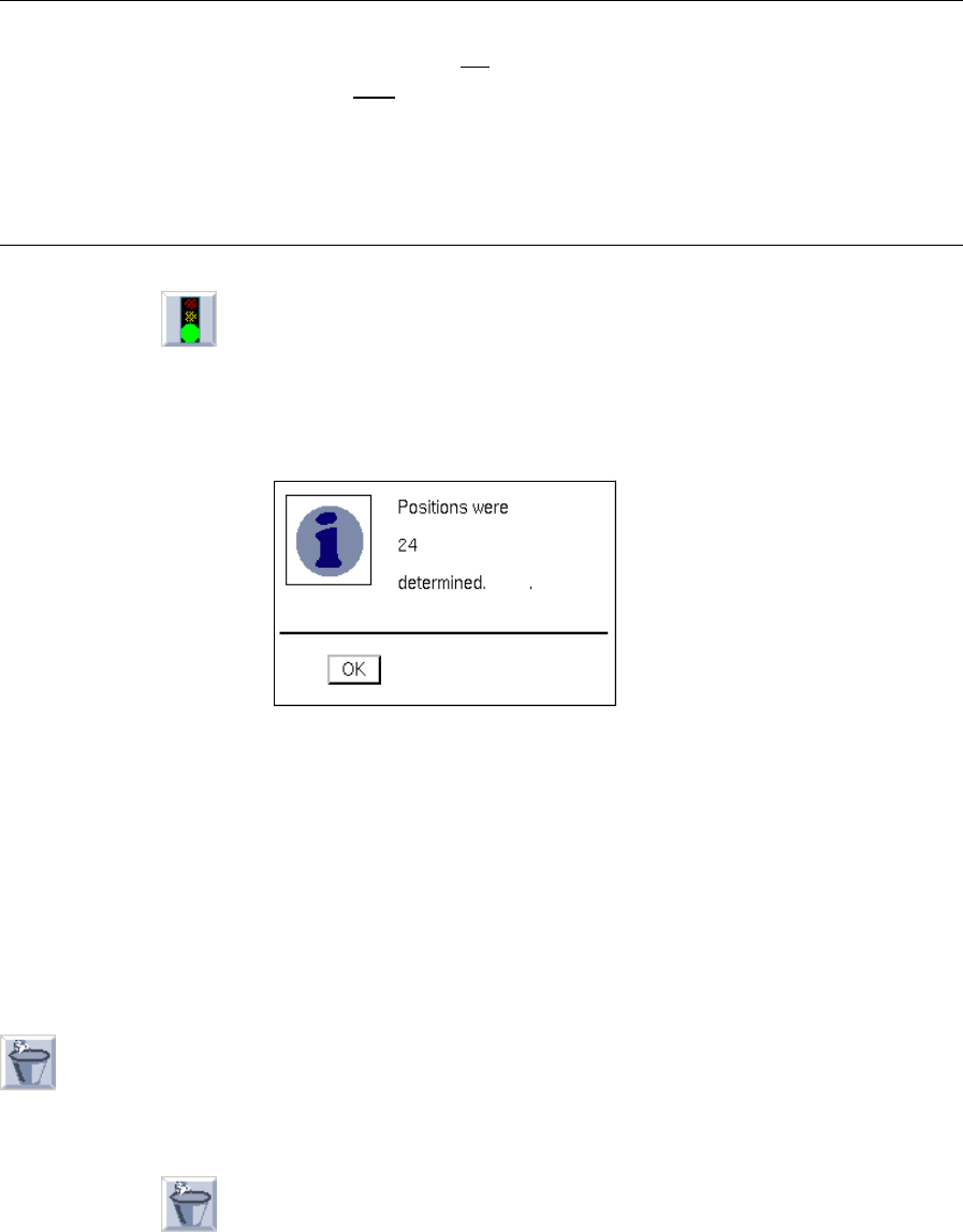
- (Start)
Clicking on this icon causes the conversion of the current CAD file (or individual lines) to be started
using the current filter.
Converting the entire file:
● Click on the icon in the command area (see Fig. 4.6.1).
Conversion is started using the selected filter.
Converting individual lines:
● Successively click on the desired lines using the left mouse button.
They are now highlighted in dark.
4 Data Management User Manual Line Computer UNIX
4.6 CAD Import Software Version 501.xx 01/99 Issue
4 - 48
NOTE
Clicking once more on a selected line using the left
mouse button will cancel the selection of the line.
Clicking on a selected line using the right
mouse button causes the entire selection to be canceled
again.
If several consecutive lines are to be selected, click on the first line of the group of lines to be selected
by clicking the left mouse button, hold down the SHIFT key while selecting the last line by a click with
the left mouse button. Every line between the two will be highlighted.
● Click on the icon in the command area.
Conversion is started using the selected filter.
After the conversion process has been successfully completed, the following dialog box opens
displaying the number of converted data records.
If the conversion could not be completed successfully, a dialog box containing a corresponding
message is displayed.
● Close the dialog box by choosing OK.
For reviewing purposes, the placement positions determined can now be displayed graphically
(see Fig. 4.6.2), or the cluster data can be edited in the "Adapt cluster data" window (see Fig.
4.6.3).
● Save the converted structure (see section 4.6.2.1).
- (Discard)
Clicking on this icon causes the converted data (not saved yet) to be discarded, and the conversion of
the current CAD file can be restarted.
● Click on the icon in the command area.
The converted data are discarded.
User Manual Line Computer UNIX 4 Data Management
Software Version 501.xx 01/99 Issue 4.6 CAD Import
4 - 49
4.6.3 Filter Editing Mode
In the filter editing mode of CAD Import, existing filters can be modified or new filters be created. In either case
this is accomplished on the basis of the currently used CAD file. The filters are not bound to the CAD file by
means of which they were created, but they can be applied to all other CAD files whose data structure matches
that of the filter.
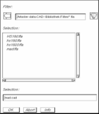
● Open the "PCB filter dialog" window by means of the "SERVICES" menu
(see section 4.6.2.2).
● Click on the "PCB filter dialog" filter selection button (see Fig. 4.6.4).
The FSB containing the file selection of all already-defined PP filters (*.fla) opens.
● Select the filter "xx.fla" by double-clicking, or enter new name on the keyboard and confirm with
OK (or RETURN).
The FSB closes and the name of the filter is transferred to the "Filter" field.
This is the name under which the subsequently determined filter definitions are saved (see
section 4.6.3.2).