00191413-01.pdf - 第554页
17.3 Description of Components and PCBs User Manual Line Computer UNIX 17.3.2 PCB 2: Focus on Packa g e Form Description Software Version 501.xx 01/99 Issue 17 - 22 FILE Save Openin g Pac kage Form Editor Defin ing pa ck…
User Manual Line Computer UNIX 17.3 Description of Components and PCBs
Software Version 501.xx 01/99 Issue 17.3.2 PCB 2: Focus on Packa
g
e Form Description
17 - 21
s
b
l
Bonding
Nozzles
Sensor
type
Placing
force
Processing Placem. head Centering Feeder
615, 618 9 2 Placin
g
Turret head in head 12 mm tape
Pack. form type GF-No.
PDC 1503.
g
f
l
mm
b
mm
s
mm
5,7 5,0 1,7
Y
X
Component
coordinate system
X
Y
Component
coordinate system
Pack. form type GF-No.
irre
g
ular FDC 1503.
g
f
Dim min. typ. max.
A--1.8
b 0.55 0.60 0.70
b
1
1.82 1.87 1.97
D 6.3 6.5 6.7
E 3.3 3.5 3.7
e
1
-3.81-
e
2
-1.27-
H
E
6.7 7.0 7.3
The pin
g
roup offset BG
Off
and the pin len
g
th B
L
are not indi-
cated and must be calculated from the followin
g
formulae (see
Fi
g
. in On-line Help:
Nozzles
Sensor
type
Processing Placem. head Centering Feeder
615, 618 9 Placin
g
Turret head in head 12 mm tape
BL
Width HE Width E
–
2
---------------------------------------------------------=
BGOff
Width HE PinLength BL
–
2
-------------------------------------------------------------------------=
Y
X
Component
coordinate system
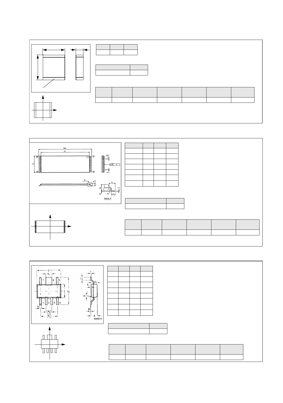
Comp5.be: Plastic 32pin 8x20mm TSOP
Symbol Min Nom Max
A--1.2
b 0.15 0.2 0.3
D 18.3 18.4 18.5
E7.98.08.1
e-0.5-
H
D
19.8 20.0 20.2
L
1
-0.8-
Package form type GF-No.
re
g
ular FDC 1502.
g
f
The pin
g
roup offset BG
Off
is not indicated and
must be calculated usin
g
the followin
g
formula
(see Fi
g
. in On-line Help):
BGOff
Width HE PinLength BL
–
2
-------------------------------------------------------------------------=
Nozzle
Sensor
type
Processing
Placem.
head
Centering Feeder
416 7 Placin
g
IC-head external 32 mm tape
Comp6.be: Micro-X / MW
Comp4.be: Multi-Layer Capacitor, Type 2220
17.3 Description of Components and PCBs User Manual Line Computer UNIX
17.3.2 PCB 2: Focus on Packa
g
e Form Description Software Version 501.xx 01/99 Issue
17 - 22
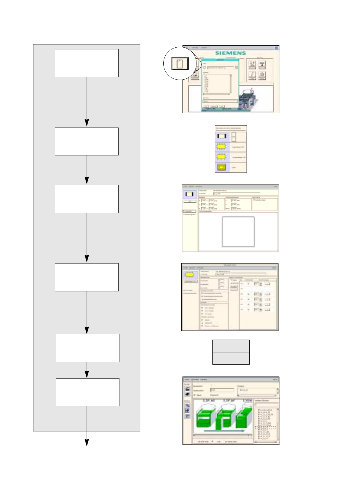
FILE
Save
Opening Package
Form Editor
Defining package
form type
Entering dimensions
Allocating package
form to a feeder
Entering handling
data
Package form description for package form 1501
continued on pa
g
e 17-24
Saving
package form data
User Manual Line Computer UNIX 17.3 Description of Components and PCBs
Software Version 501.xx 01/99 Issue 17.3.2 PCB 2: Focus on Packa
g
e Form Description
17 - 23
17.2.2.1 Package Form Description
A) Description of a PDC using package form 1501 as an example
To open the Package Form Editor for package form 1501, proceed as follows:
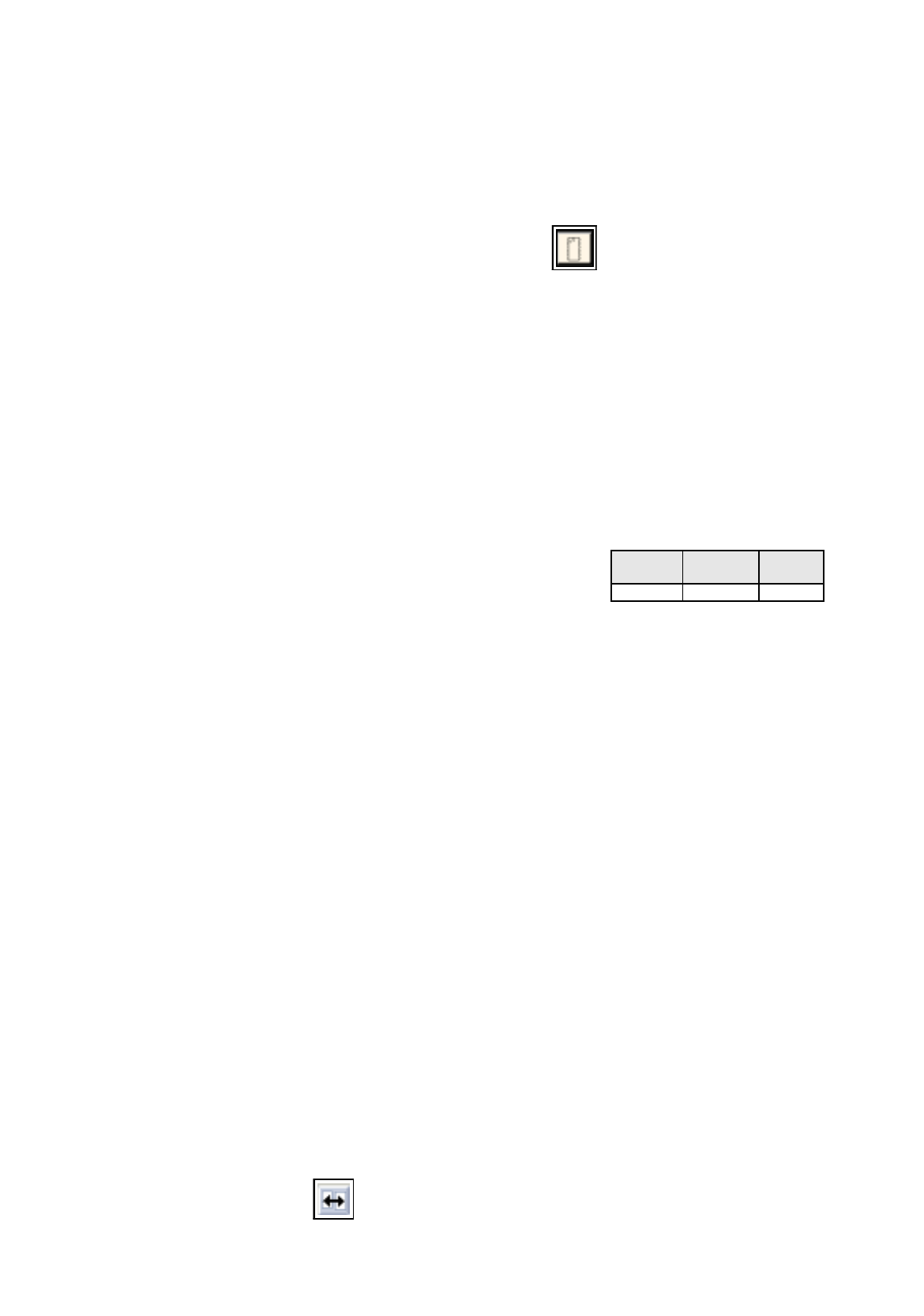
1. On the desktop click on the icon of the Packa
g
e Form Editor .
The file selection window is opened.
2. Click on the
Selection
editin
g
field.
3. Enter the packa
g
e form number, here:
1501.gf
and click on the
OK
button.
The Packa
g
e Form Editor with the packa
g
e form t
y
pe selection window is opened.
To define the package form type „PDC“ for package form 1501, proceed as follows:
4. In the packa
g
e form t
y
pe selection window click on the t
y
pe
PDC
.
The selection window is closed.
5. In the Packa
g
e Form Editor click on the
Comment
editin
g
field, enter a uni
q
ue comment
,
here:
Chip
2220
.
To enter the dimensions for package form 1501, proceed as follows:
6. In the
Nominal Dimensions
editin
g
area enter the dimensions of the packa
g
e form
(
click on the editin
g
field, enter value, confirm b
y
pressin
g
the Enter ke
y)
, here: see chart:
The tolerances are entered automaticall
y
.
The packa
g
e form is displa
y
ed with the tolerance ran
g
e.
7. For this example the default values of the editin
g
areas Packa
g
in
g
tolerances and Features are adopted,
no entries are re
q
uired.
To enter the handling data for package form 1501, proceed as follows:
8. Activate the
Handling data
button.
The screen for enterin
g
the handlin
g
data is displa
y
ed.
9. Activate the
Nozzle
button in the command area.
10. Click on the
Create
button.
The Nozzle t
y
pe selection window containin
g
a list of the nozzle t
y
pes is loaded.
11. Click on a nozzle
,
here:
615
.
The selection window closes, the nozzle is transferred to the view area.
12. Select all other nozzles re
q
uired accordin
g
l
y
, here:
618
.
13. Activate the
Sensor type
button.
14. Click on the
Create
button.
The
Sensor type
selection window containin
g
a list of the sensor t
y
pes is opened.
15. Click on a sensor t
y
pe, here:
9
.
The selection window closes, the sensor t
y
pe is transferred to the view area.
16. In the ’Handlin
g
values’ editin
g
area, enter the applicable value in the
Placement force
field, here:
2
.
17. In the ’Centerin
g
’ selection box, activate the applicable buttons, here:
Centering in head
.
18. In this example, the preselected settin
g
s for the handlin
g
values, the handlin
g
instructions and the ’Acce-
leration’ special handlin
g
option can be accepted as the
y
are. No chan
g
es are re
q
uired.
19. Click on the
Save
option on the
FILE
menu.
The data are now saved.
To allocate a feeder to package form 1501, proceed as follows:
20. Click on the
Starting Feeder Editor
option on the
SERVICES
menu.
The Feeder Editor is opened.
21. Activate the
Allocate
icon .
X
(Length l)
Y
(Width b)
Z
(Height s)
5.7 5 1.7