00191413-01.pdf - 第381页
User Manual Line Computer UNIX 12 Production Tools / S tation and Line Configuration Software Version 501.xx 01/99 Issue 12.1 Configuration Editor 12 - 19 12.1.3.5 Main Window of Machine Options E ditor "Nozzle Chan…
12 Production Tools / Station and Line Configuration User Manual Line Computer UNIX
12.1 Configuration Editor Software Version 501.xx 01/99 Issue
12 - 18
12.1.3.4 Main Window of Machine Options Editor "Head"
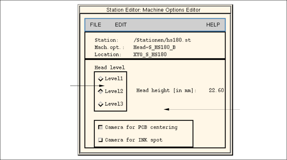
Fig. 12.1.6 Machine Options Editor "Head" (location "Gantry HS-180")
POSSIBLE SETTINGS for the machine option "Head"
- Camera for PCB centering PCB centering with/without camera
- Camera for Ink spot ink dot recognition with/without camera
- Head level selection of head mounting position in 3 stages
(does not apply to SIPLACE head) (14.60, 22.60 and 30.60 mm)
depending on the respective head type
(e.g. "Level 3" for 30mm head)
setting area
settings for"Head level"
(does not apply to
"SIPLACE head)
User Manual Line Computer UNIX 12 Production Tools / Station and Line Configuration
Software Version 501.xx 01/99 Issue 12.1 Configuration Editor
12 - 19
12.1.3.5 Main Window of Machine Options Editor "Nozzle Changer"
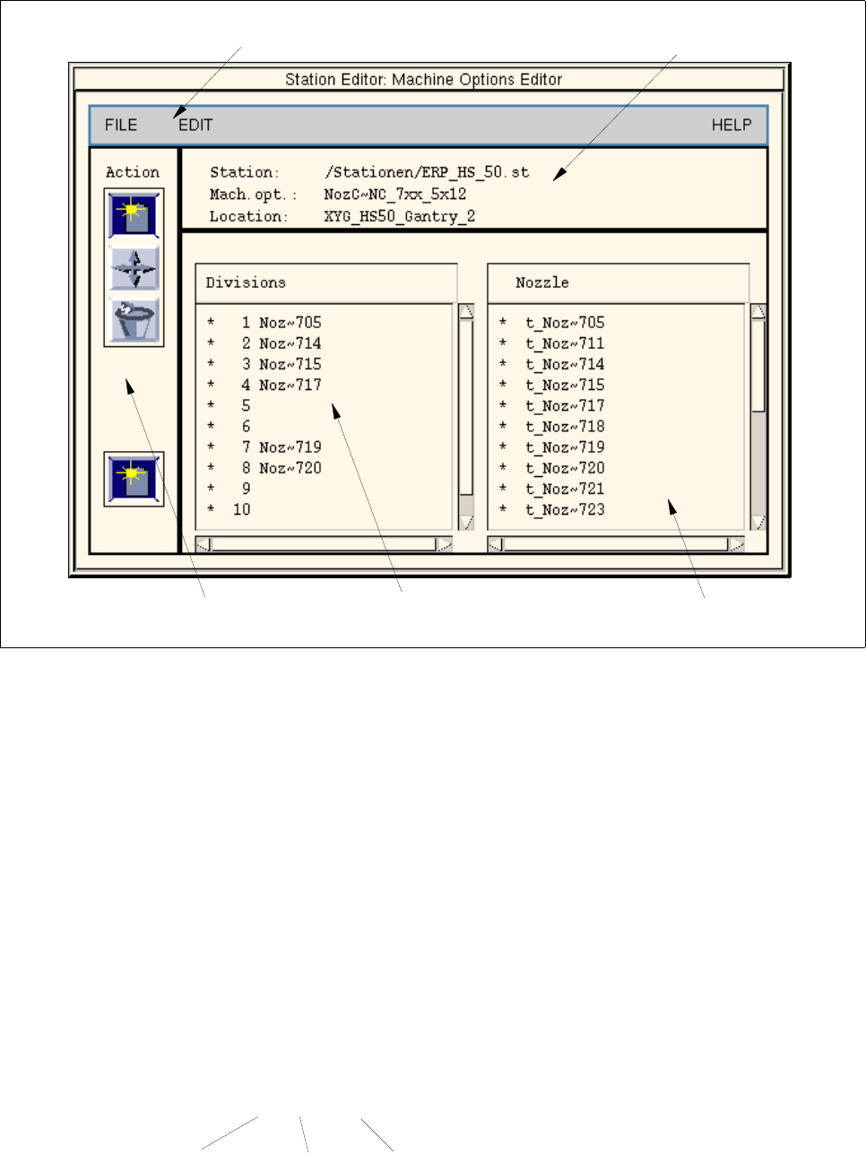
Fig. 12.1.7 Machine Options Editor "Nozzle Changer" (example HS-50)
Selection fields
The selection fields are located in the main window of the component editor (see Fig. 12.1.7) below the
identification field.
- Divisions
The manufacturer has provided all compartments of the changer with numbers. These
numbers are displayed in the selection field. A varying number of nozzle compartments is available
depending on the nozzle changer type.
- Nozzles
All factory-defined nozzles are listed in this selection field.
Entries in the selection field contain the following information:
Example: t_Pip~ 752
selection field "Divisions"
command area
menu bar
identification field
Selection field "Nozzles"
default nozzle
nozzle type no.
12 Production Tools / Station and Line Configuration User Manual Line Computer UNIX
12.1 Configuration Editor Software Version 501.xx 01/99 Issue
12 - 20
Command Area
The commands are symbolized by means of icons. They determine the mode (selection mode, allocation mode
or deletion mode) in which the Configuration Editor is to operate.
NOTE
Upon opening, the Configuration Editor is initially in the selection mode. If nozzles are allocated in the
Configuration Editor with the aid of the Machine Options Editor, they are deemed to be configured and
their allocation cannot
be changed any more in the Set-Up Editor (see chapt. 13, section 13.1.3.6).
If the nozzle changer is to be configured differently for the various setups, it is important that the allocation
of the nozzles be carried out only in the Set-Up Editor.
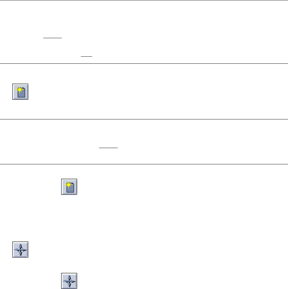
- Create
If this icon is active, a nozzle can be allocated to a location in the Nozzle Changer.
NOTE
If the Machine Options Editor for the nozzle changer of an HS-50 placement station is invoked, a second
icon for "Create" is displayed in the bottom
portion of the command area (see Fig. 12.1.7). A second
nozzle changer (option) can be set up when this icon is activated.
● Click on icon in the command area.
● Click on the target location in the Divisions selection field.
● Click on a nozzle in the Nozzle selection field.
The number of the nozzle is then entered in the target location.
- Move
If this icon is active, a nozzle can be moved to another location within a Nozzle Changer.
● Click on icon in the command area.
● Click on the target location in the Divisions selection field.
● Click on the nozzle you wish to move.
The moved nozzle is displayed in the target location (division).