00191413-01.pdf - 第204页
6 Product / Package Form User Manu al Line Computer UNIX 6.1 Package Form Editor Software Version 501.xx 01/99 Issue 6 - 26 Special Handl ing for Nozzle Types 2xx, 4xx (IC-Head F3) or 6xx Special handling during th e pic…
User Manual Line Computer UNIX 6 Product / Package Form
Software Version 501.xx 01/99 Issue 6.1 Package Form Editor
6 - 25
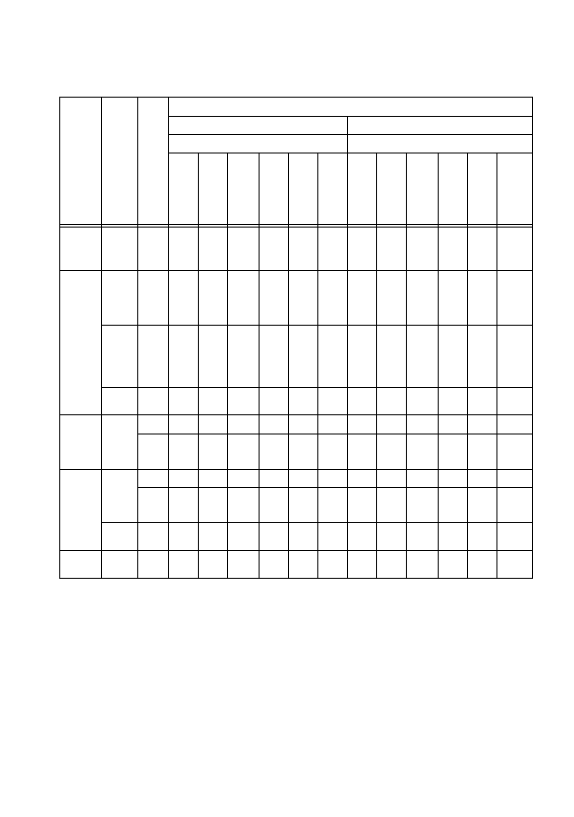
Minimum and Maximum Axis Acceleration Values
Machine Type
Head Type
Nozzle Type
Acceleration Values
Minimum Acceleration Maximum Acceleration
Axis Axis
x
g
y
g
Star
g
z
↑
g
z
↓
g
dp
(d)
rad/
s
2
x
g
y
g
Star
g
z
↑
g
z
↓
g
dp
(d)
rad/
s
2
S-20
S-23
HS-50
12-
noz.
RV-
Head
7xx
0,1 0,1 0,1 0,1 0,1 0,1 4 4 5,8 5,3 5,3 3100
F4
12-
noz.
RV-
Head
7xx
0,1 0,1 0,1 0,1 0,1 0,1 4 4 5,8 5,3 5,3 3100
6-
noz.
RV-
Head
7xx /
8xx
0,1 0,1 0,1 0,1 0,1 0,1 4 4 5,2 5,3 5,3 1282
IC-
Head
4xx
0,1 0,1 0,1 0,1 0,1 0,1 4 4 -- 1,3 1,3 641
S15
12-
noz.
RV-
Head
3xx
-- -- -- -- -- -- -- -- -- -- -- --
6xx
-- -- -- 35% 35% 35% -- -- -- 5,3 5,3 3100
F3
12-
noz.
RV-
Head
3xx
-- -- -- -- -- -- -- -- -- -- -- --
6xx
-- -- -- 35% 35% 35% -- -- -- 5,3 5,3 3100
IC-
Head
4xx
35% 35% -- 35% 35% 35% 4 4 -- 1,3 1,3 641
HS-180 IC-
Head
2xx
35% 35% -- 35% 35% 35% 4 4 -- 1,3 1,3 641
Tab. 6.1 - 1 Acceleration Values
6 Product / Package Form User Manual Line Computer UNIX
6.1 Package Form Editor Software Version 501.xx 01/99 Issue
6 - 26
Special Handling for Nozzle Types 2xx, 4xx
(IC-Head F3)
or 6xx
Special handling during the pick-up, centering and placement processes can be defined for the nozzle types
mentioned above, i.e. the acceleration of the selected axes (or processes) is reduced to 35%
.
Procedure (Example for Nozzle Type 2xx):
●
In the view area (see Fig. 6.1.9) activate the "Special handling" button adjacent to the nozzle of
the desired type.
●
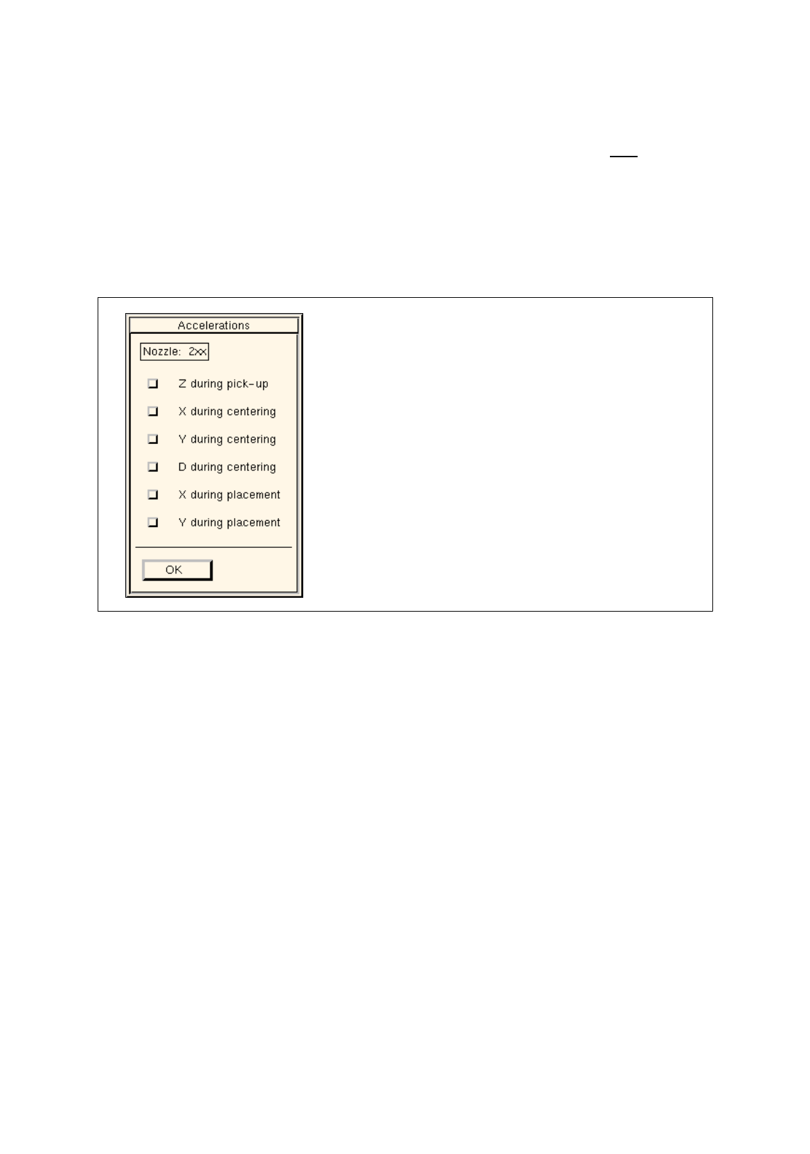
Click on the ">>" button. The following dialog box opens.
Fig. 6.1.10 Dialog Box for Selecting the "Acceleration" Special Handling Option (Example: Nozzle Type 2xx)
Setting possibilities
Z during pick-up
(not for 6xx) reduced acceleration of the z-axis of the RV or IC head
on picking up the component from the pick-up position
X during centering
(not for 6xx) reduced acceleration of the X-axis during transporting the
component from the camera to the placement position by means
of the IC head
Y during centering
(not for 6xx) reduced acceleration of the Y-axis during transporting the
component from the camera to the placement position by means
of the IC head
D during centering
reduced acceleration of the dp1- and dp2-axes of the RV head
and of the d-axis of the IC head upon centering the component
X during placement
(not for 6xx) reduced acceleration of the X-axis during transporting the
component from the pick-up to the placement position by means
of the RV head
reduced acceleration of the X-axis during transporting the
component from the IC camera to the placement position by
means of the IC head

User Manual Line Computer UNIX 6 Product / Package Form
Software Version 501.xx 01/99 Issue 6.1 Package Form Editor
6 - 27
Y during placement
(not for 6xx) reduced acceleration of the Y-axis during transporting the
component from the pick-up to the placement position by means
of the RV head
reduced acceleration of the Y-axis during transporting the
component from the IC camera to the placement position by
means of the IC head.
●
Activate the button next to the desired axis.
(In the case of nozzle type 6xx only the buttons for the z and d-axes can be activated).
●
Confirm the setting by clicking on
OK
.
The dialog box closes.
The acceleration of the selected axes is reduced to 35% for all nozzles of the selected type.
This value is entered in the appropriate editing fields in the view area.
NOTE
If the associated button was not activated for all axes (processes), the corresponding editing fields
only contain a broken line (----). This indicates that the acceleration of at least one axis has not been
reduced (in the case of nozzle type 6xx this is either the z or d-axis).
Special Handling for Nozzles of the Types 4xx, 7xx and 8xx on the Machine Types SIPLACE
80S-20/23/HS-50 and 80F
4
/F
5
The "Acceleration" special handling option can be selected for each nozzle of the types mentioned above
as well as individually for each axis. This means that the respective axis will move at the acceleration
corresponding to the value entered.
Procedure (Example for Nozzle 820):
●
In the view area (see Fig. 6.1.9) click on the "Special handling" button next to the desired nozzle.
●
Click on the ">>" button. The following dialog box opens.