00191413-01.pdf - 第224页
6 Product / Package Form User Manu al Line Computer UNIX 6.1 Package Form Editor Software Version 501.xx 01/99 Issue 6 - 46 Fig. 6.1.23 Example "Ball Grid Array comprising a single grid group" Fig. 6.1.24 Examp…

User Manual Line Computer UNIX 6 Product / Package Form
Software Version 501.xx 01/99 Issue 6.1 Package Form Editor
6 - 45
6.1.3.3 Description of a Package Form of the "BGA" Type
For optical centering by means of the Vision System, the package form of a BGA must be completely described.
For this purpose, following the entries of the nominal dimensions (see section 6.1.2.5) the following steps must
be performed:
-
description of the grid groups
-
description of the BGA models
First the window for the description of the grid group (see Fig. 6.1.25) is opened. Only after a grid group has
been defined can the window for the description of a ball model be opened (siehe Fig. 6.1.26).
Explanation of Terms Used in GF-Data for the Description of "Ball" Models and Grid Groups
of the "BGA" Package Form Type:
-
BGA
Geometry of the "ball"
A model is defined by:
ball radius
[µ
m]
radius tolerance
[µ
m]
-
Grid group
Group of "balls" of the same model, arranged in a grid array
(grid element spacing e.g. 1.27 mm)
A grid group is defined by:
number of (vertical) columns
number of (horizontal) rows
grid width
[µ
m]
grid height [
µ
m]
position of grid group center
(x and y-offsets) relative to the
component center
[µ
m]
(each grid group is symmetric
to the group center).
6 Product / Package Form User Manual Line Computer UNIX
6.1 Package Form Editor Software Version 501.xx 01/99 Issue
6 - 46
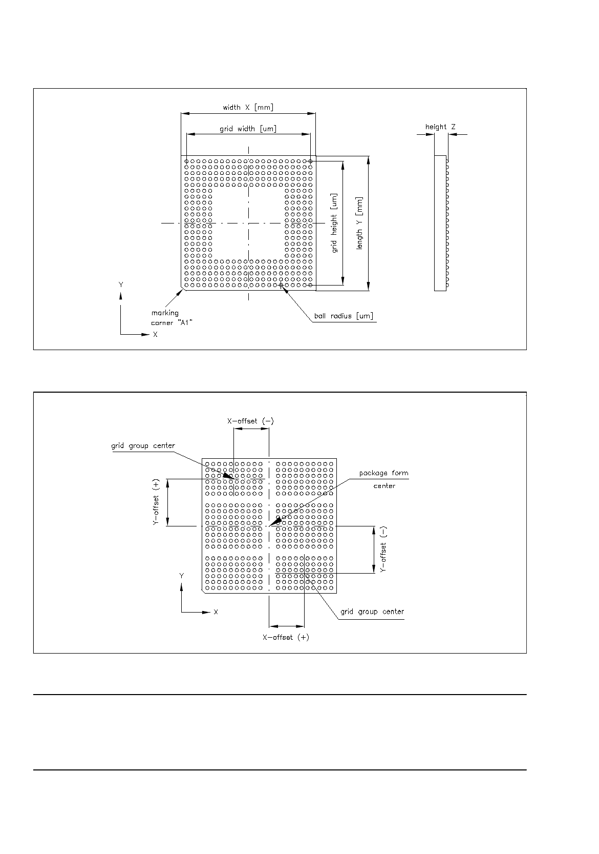
Fig. 6.1.23 Example "Ball Grid Array comprising a single grid group"
Fig. 6.1.24 Example "Ball Grid Array comprising 6 grid groups"
NOTE
For component centering by means of the Vision System, the component is placed onto the optical centering
station so that the marking of corner "A1" (see Fig. 6.1.23) is visible in the lower left corner of the Vision
System monitor. Corner "A1" can be identified by a bevel, notch, mark or the like.
User Manual Line Computer UNIX 6 Product / Package Form
Software Version 501.xx 01/99 Issue 6.1 Package Form Editor
6 - 47
Creating a Grid Group
●
Click on
Create
in the command area of the main window (see Fig. 6.1.1).
The window for editing the grid group data is opened (see Fig. 6.1.25), and a ball is displayed in
the view area of the main window. .
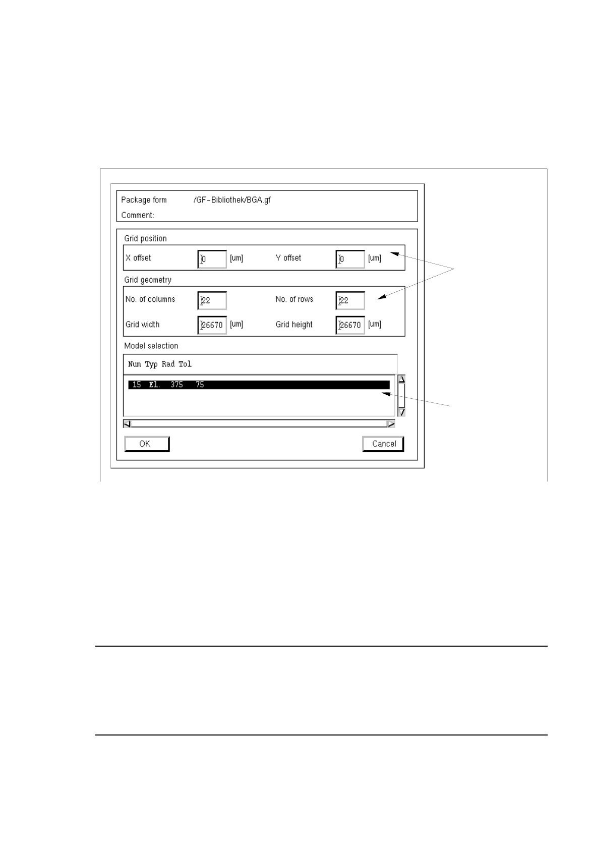
Fig. 6.1.25 Window "Grid Group Description" (with values for the grid geometry already entered)
Procedure for Editing the Grid Group Data:
●
Click on the individual editing fields and enter the values.
●
After the data have been entered, click on
OK
to confirm your entries.
If the entered values are correct, the window is closed and the window for the model description is
opened containing a display of the defined grid group (see Fig. 6.1.3).
NOTE
If invalid values were entered, a dialog box containing a corresponding error message is displayed
(see page 6 - 15). The fields containing the invalid values are surrounded by a red frame. The dialog
box must be acknowledged by clicking on
OK
first. Thereafter, the entries can be corrected and con-
firmed by clicking on "OK".
editin
g
fields
selection field
"Models"