00191413-01.pdf - 第156页
4 Data Management User Manu al Line Computer UNIX 4.6 CAD Import S oftware Version 501.xx 01/99 Issue 4 - 46 - Change cluster data The clus ter size calcula ted durin g conver sion of the place ment da ta from the outerm…
User Manual Line Computer UNIX 4 Data Management
Software Version 501.xx 01/99 Issue 4.6 CAD Import
4 - 45
- CAD data
This menu item is used to return to the display of the CAD data if the graphical display of the deter-
mined PCB structure is active (see Fig. 4.6.2).
● Select the SERVICES --> CAD data menu item.
The display is switched back to the CAD data display (see Fig. 4.6.1).
- Graphical data
Following the conversion, it is possible to display the determined PCB structure graphically.
To obtain a clearer display of the PCB, various display options for displaying the graphical elements
can be selected from the setting area. It is possible, for example, to display only placement positions
in the vie area if only these are required. The procedure to be followed is identical to the procedure in
the PCB Editor (graphic mode) and is described in detail in chapt. 8, section 8.1.3.4.
● Select the SERVICES --> Graphical data menu item.
The main window of CAD Import is switched to the graphical display mode (see Fig. 4.6.2).
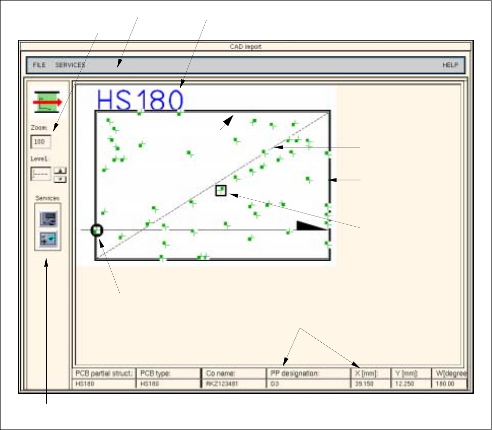
Fig. 4.6.2 "CAD-Import" Main Window (Display of the Graphical Data)
PCB zero point
Setting area
Menu bar
Outline of PCB
(cluster size)
Offset vector
Name of PCB structure
Editing field
for zooming
Selected placement
position
Data of the selected
placement position
4 Data Management User Manual Line Computer UNIX
4.6 CAD Import Software Version 501.xx 01/99 Issue
4 - 46
- Change cluster data
The cluster size calculated during conversion of the placement data from the outermost placement
positions, can be transformed into its actual size in a separate window of the CAD Import. In addition,
the selected coordinate system can be changed as well.
● Select the SERVICES --> Change cluster data menu item.
The "Adapt cluster data" window opens (see Fig. 4.6.3).
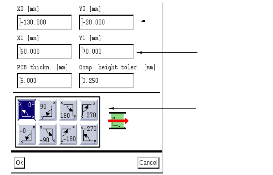
Fig. 4.6.3 "Adapt cluster data" Window
Input Possibilities:
- X0
Vector from the PCB zero point to any corner of the PCB in x-direction.
- Y0
Vector from the PCB zero point to any corner of the PCB in y-direction.
- X1
Vector from the previously defined corner to the opposite corner of the PCB in x-direction. This value
represents the length of the PCB.
- Y1
Vector from the previously defined corner to the opposite corner of the PCB in y-direction. This value
represents the width of the PCB.
Dimensions of PCB
(cluster size or offset
vector)
Vector to any one corner
of the PCB
Position of PCB in the
machine
User Manual Line Computer UNIX 4 Data Management
Software Version 501.xx 01/99 Issue 4.6 CAD Import
4 - 47
- PCB thickn.
Thickness of the PCB in mm
5 mm are entered as the default value for the maximum value.
- Comp. height toler.
Specifies the max. permissible lead bending value of a component in
1
/
1000
mm.
An entry is only required if a coplanarity check is to be performed.
As default value 250 µm are entered.
- Coordinate systems
These icons permit you to set the position of the coordinate system of the CAD data in relation to the
coordinate system of the machine, with reference to the direction of PCB travel.
If a mirrored coordinate system is selected (- 0°, - 90°, -180° or - 270°), all angles of the placement
positions are additionally turned by 180°.
Editing cluster data:
● Position the mouse cursor in the desired editing field and perform the changes using the key-
board.
● If required, change the angle between the machine coordinate system and the PCB coordinate
system by clicking on the appropriate icon.
● Click on OK.
The "Adapt cluster data" window closes.
If the graphical data display mode was selected in CAD Import, the PCB is displayed in the dis-
play area together with the modified cluster data (see Fig. 4.6.2).
4.6.2.3 Command Area
The commands are symbolized by icons.
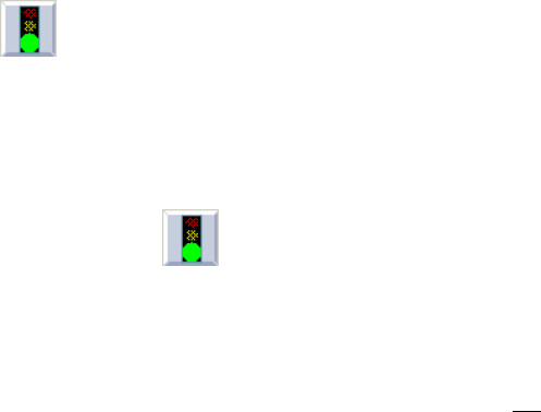
- (Start)
Clicking on this icon causes the conversion of the current CAD file (or individual lines) to be started
using the current filter.
Converting the entire file:
● Click on the icon in the command area (see Fig. 4.6.1).
Conversion is started using the selected filter.
Converting individual lines:
● Successively click on the desired lines using the left mouse button.
They are now highlighted in dark.