00191413-01.pdf - 第263页
User Manual Line Computer UNIX 8 Product / PCB Software Version 501.xx 01/99 Issue 8.1 PCB Editor 8 - 25 8.1.4 Cluster Editor Window A Cluste r Editor c an be o pened for each PCB type gene rated (s ee desc ription on pa…
8 Product / PCB User Manual Line Computer UNIX
8.1 PCB Editor Software Version 501.xx 01/99 Issue
8 - 24
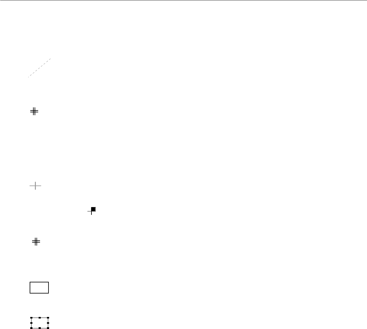
Offset vector
connects the zero point of a substructure to the zero point of the superior substructure and hence
corresponds to the offset or displacement vector between the two coordinate systems of these
substructures.
PCB fiducial
This symbol indicates the position of a PCB-related fiducial.
It is always displayed in the shape of a double cross, irrespective of the actual shape of the fiducial.
Ink spot
l This symbol indicates the position of the fiducials defined as inkspots.
It is always displayed in the shape of a dot, irrespective of the actual shape of the fiducial.
Placement position (color green)
This symbol indicates the position of the placement position or the zero point of the coordinate
system of the placement position.
To identify the position of pin 1, the quadrant in which pin 1 is located is highlighted in solid color.
Example :
Placement position fiducial
This symbol indicates the position of a PP-related fiducial.
It is always displayed in the shape of a double cross, irrespective of the actual shape of the fiducial,
and it is significantly smaller than the symbol of a PCB fiducial.
Frame around a selected placement position and/or substructure
The frame marks the outline of the currently selected substructure.
The frame marks the currently selected placement position.
Frame around placement position(s) or a substructure
The frame marks the outline of a substructure which is linked to the currently selected sub-
structure.
The frame marks the placement positions which are linked to the currently selected placement
position.
User Manual Line Computer UNIX 8 Product / PCB
Software Version 501.xx 01/99 Issue 8.1 PCB Editor
8 - 25
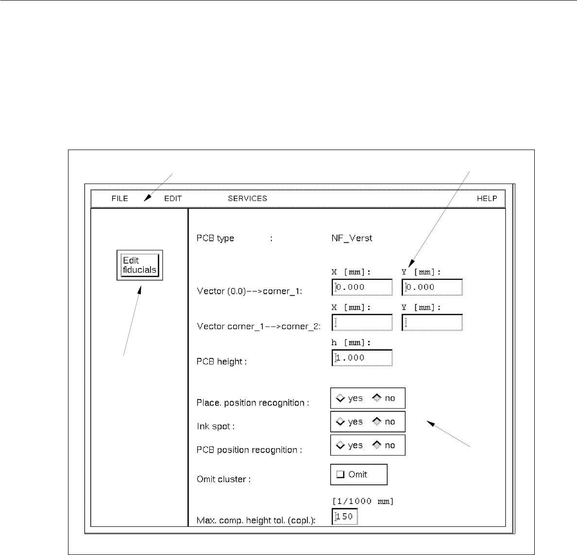
8.1.4 Cluster Editor Window
A Cluster Editor can be opened for each PCB type generated (see description on page 8 - 10).
In the following, the different areas of the Cluster Editor window and their functions are explained.
Fig. 8.1.8 Window "Cluster Editor"
The window is subdivided as follows:
- Menu bar
- Editing area
- Setting area
- Command button
menu bar
editing area
command button
setting area

8 Product / PCB User Manual Line Computer UNIX
8.1 PCB Editor Software Version 501.xx 01/99 Issue
8 - 26
Menu Bar
The menu bar contains the menus "FILE", EDIT", "SERVICES" and "HELP".
A detailed description of the "EDIT" menu is contained in section 8.1.4.1 and a description of the "SERVICES"
menu is contained in section 8.1.4.2.
NOTE
Since the functions and operation of the "FILE" and "HELP" menus are similar to those in other application
programs of the line computer, they are described comprehensively in chapt. 2.
Editing area (see section 8.1.4.3)
All PCB-specific data that are required for the description of a PCB, the so-called cluster, are entered in this area.
- The cluster description contains the following data:
- Dimensions of the PCB such as length, width and height
- Process data for the production of the PCB, such as PP position recognition on/off, ink spot recogni-
tion on/off, PCB position recognition on/off, placement on/off (omit cluster) and the max. component
height tolerance for the coplanarity measurement
- Fiducial sets and fiducials
Setting area (see section 8.1.4.4)
The operational sequence of the placement process can be defined in this area by activating/deactivating the
respective buttons (e.g. assembly with or without PCB position recognition).
"Edit fiducials" command button
The window of the Fiducial Editor is opened by clicking on this button (see Fig. 8.1.10).