00191413-01.pdf - 第194页
6 Product / Package Form User Manu al Line Computer UNIX 6.1 Package Form Editor Software Version 501.xx 01/99 Issue 6 - 16 6.1. 2.6 View are a - "Vision data" Screen The current pa ckage for m is graph ically …
User Manual Line Computer UNIX 6 Product / Package Form
Software Version 501.xx 01/99 Issue 6.1 Package Form Editor
6 - 15
Procedure to be followed for editing package form data:
Editing new GF-data:
●
Click on editing field "X" in the "Nominal dimensions" editing area, enter value and complete the
entry with RETURN.
●
Click on editing field "Y", enter value and complete the entry with RETURN.
In the editing fields for the width and length tolerances, and in the "Packaging tolerance" editing
area the automatically calculated default values are displayed.
●
Click on editing field "Z", enter value and complete entry with RETURN.
In the editing field for the height tolerance the automatically calculated default value is displayed.
NOTE
The default values derived from the values entered will only be computed if each entry is
completed by pressing RETURN.
●
Click on editing field "X" in the "Body" editing area, enter value and complete the entry with
RETURN.
●
Click on editing field "Y", enter value and complete the entry with RETURN.
Changing existing data:
●
Click on desired editing field (position cursor in front of the value).
●
Delete value using the DELETE key.
●
Enter new value and complete the entry by pressing RETURN.
NOTE
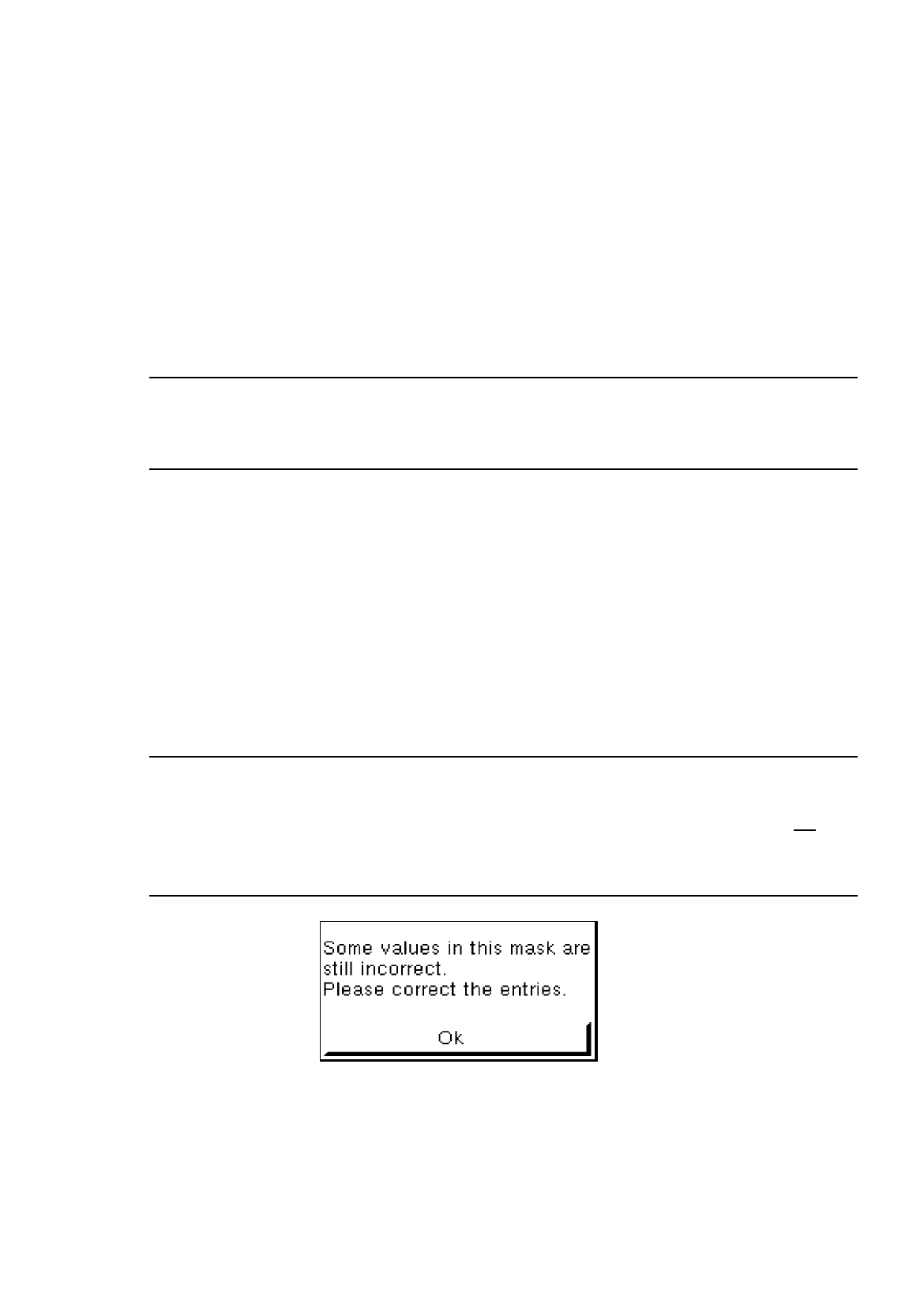
If invalid values or characters (e.g. letters or a comma as decimal point) were entered, the field being
edited is surrounded by a red frame and the entry must be corrected. If the RETURN key is not
pres-
sed after each entry, faulty fields will not be shown in a red frame until the GF-file is saved , and the
following dialog box will be opened:
●
Close dialog box by selecting
OK
and correct the faulty entries.

6 Product / Package Form User Manual Line Computer UNIX
6.1 Package Form Editor Software Version 501.xx 01/99 Issue
6 - 16
6.1.2.6 View area - "Vision data" Screen
The current package form is graphically represented in the view area. When the dimensions are edited in the
"Nominal dimensions" and "Body" editing areas, the display is automatically updated.
-
The package (body) is drawn as a rectangle with a solid black line.
-
The two rectangles drawn with a broken black line reflect the nominal dimensions including negative
and positive tolerance values. (The nominal dimensions themselves are not displayed).
-
Created pin models are depicted as filled dark-blue rectangles in accordance with their length and
width dimensions. Their color changes depending on their state (see color explanation below).
-
Created ball models are depicted as filled dark-blue circles in accordance with their diameters. Their
color changes depending on their state.
Explanation of colors
Dark-blue pin/ball --> non-selected group for which a model is defined.
Gray-blue pin/ball --> non-selected group for which no model has been defined yet.
Dark-green pin/ball --> selected group for which a model is defined.
Light-green pin/ball --> selected group for which no model has been defined yet.
Single-click on a pin or a ball with the color
dark-blue or gray-blue --> draws a black frame around the group to which the clicked-on object
belongs.
The pins/balls contained in the selected group are displayed in
dark-green or light-green.
All pins/balls contained in the non-selected groups for which the same
model was defined, are displayed in dark-green.
Single-click on a pin or a ball with the color
dark-green or light-green --> reverses the selection
NOTE
For the windows required for changing group or model data to open, the clicking sequence described below
must be observed.
Opening the window for changing group data
●
Single-click on any pin (see Fig. 6.1.1) or ball (see Fig. 6.1.3) of the desired group.
The whole group is highlighted.
●
Select pin or ball once more by (quickly) double-clicking.
The window for editing the group data is opened (see Fig. 6.1.20).

User Manual Line Computer UNIX 6 Product / Package Form
Software Version 501.xx 01/99 Issue 6.1 Package Form Editor
6 - 17
Opening the window for entering or changing model data
●
Select desired pin or ball by (quickly) double-clicking.
The window for editing the model data is opened (see Fig. 6.1.21 and Fig. 6.1.26).
NOTE
The window for editing the group or model data can also be opened using the commands "Group"
or "Pin/Ball" (see section 6.1.2.4).