00191413-01.pdf - 第402页
13 Production Tools / Set-Up User Manu al Line Computer UNIX 13.1 Set-Up Editor (Feeder Part and W PC Editors) Software Version 501.xx 01/99 Issue 13 - 4 Menu Bar The menu bar contai ns the menus "FIL E", "…
User Manual Line Computer UNIX 13 Production Tools / Set-Up
Software Version 501.xx 01/99 Issue 13.1 Set-Up Editor (Feeder Part and WPC Editors)
13 - 3
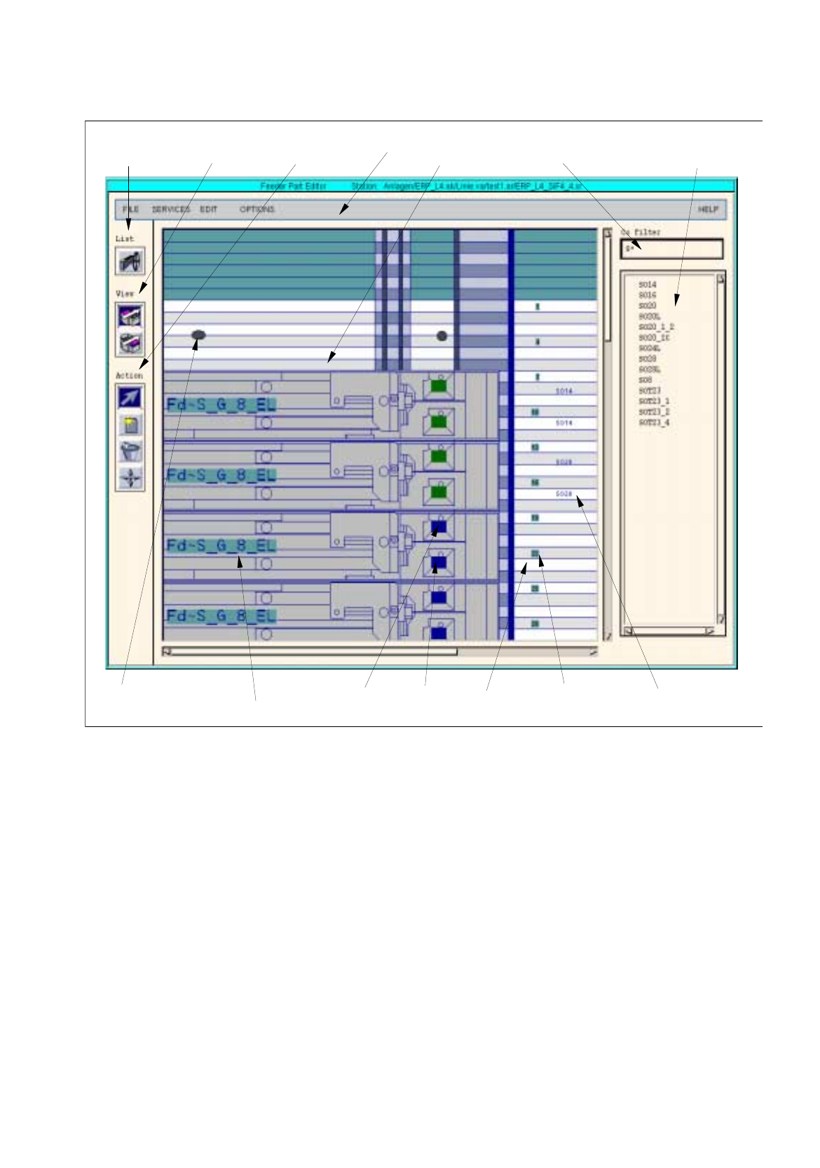
Fig. 13.1.2 Main Window of Feeder Part Editor
The main window of the Feeder Part Editor is subdivided into the following areas:
-
Menu bar
-
Command area "View"
-
Command area "Lists"
-
Command area "Action"
-
Display area
-
Filter field "Component filter"
-
Selection field "Components"
menu bar filter field selection field
"Components"
command
feeder track
division 2
track number
name of the
command
area "Lists"
spherical
cap
displa
y
area
"Component filter"
(
8mm-tape feeder, electr.
)
command
area "View"
area "Action"
component set up
division 1
13 Production Tools / Set-Up User Manual Line Computer UNIX
13.1 Set-Up Editor (Feeder Part and WPC Editors) Software Version 501.xx 01/99 Issue
13 - 4
Menu Bar
The menu bar contains the menus "FILE", "SERVICES", "EDIT", "OPTIONS" and "HELP".
The "SERVICES" menu is described in section 13.1.3, the "EDIT" menu in section 13.1.4.
NOTE
The functions and the operation of the menus "FILE", "OPTIONS" and "HELP" are similar to those of other
application programs of the line computer and are described in detail in chapt. 2 "General Information on
Using the Program".
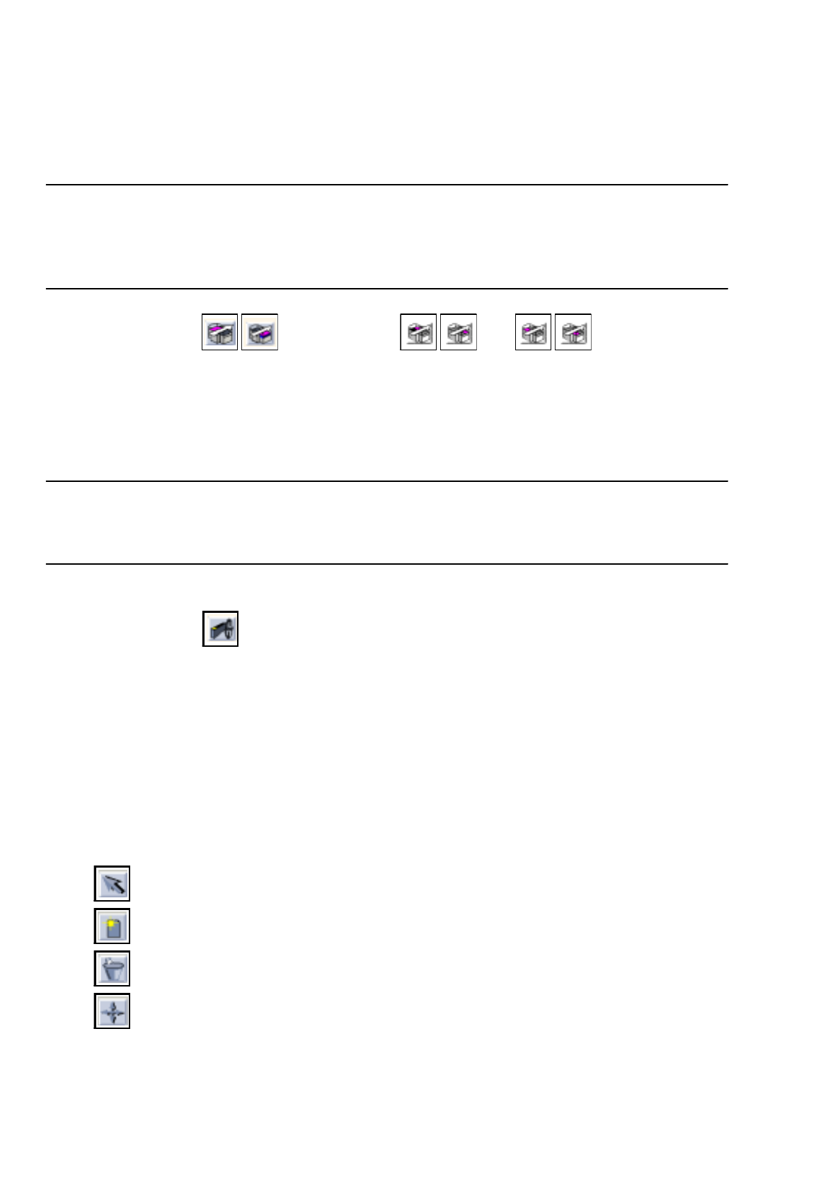
Command area "View"
( HS-50 / PA1 PA 2 )
In this command area, the icons for the left and right feeder parts are displayed. By clicking on the icons it is
possible to switch from the display area of one feeder part to the other feeder part of a station.
The upper icon refers to the left feeder part, the lower icon to the right feeder part. The arrow reflects the direction
of travel.
The icon corresponding to the current feeder part is highlighted in each case.
NOTE
If the Feeder Part Editor is opened for an HS-50, icons for the left and right feeder parts are displayed for each
of the two processing areas (PA).
Command area "Lists"
In this command area the "Feeder list" icon is displayed by means of which the feeder list can be opened. In
the feeder list all possible feeders, modules, waffle-pack trays and waffle-pack tray carriers are contained. They
can be selected individually and allocated to the tracks in the display area of the main window.
Moreover, the feeder list can be opened from the FILE menu by means of the "Feeder list" option.
For a detailed description refer to section 13.1.3.1.
Command area "Action"
In this command area the icons are displayed by means of which the following actions can be executed:
-
selecting
-
creating
-
deleting
-
moving
A detailed description of the icons is contained in section 13.1.5.

User Manual Line Computer UNIX 13 Production Tools / Set-Up
Software Version 501.xx 01/99 Issue 13.1 Set-Up Editor (Feeder Part and WPC Editors)
13 - 5
Display area
In the display area, the feeder part of a station with the individual tracks is displayed symbolically (see
Fig. 13.1.2).
If feeders or waffle-pack trays have already been defined for the feeder part displayed, these will be displayed
on their respective tracks when the Feeder Part Editor is opened.
The tracks are displayed in gray and white. The black dots symbolize the spherical caps of the feeder part.
The track number is indicated at the right edge of the feeder part. By moving the lower scroll bar toward the
right this area becomes visible.
The feeders are represented in gray with blue contours. The divisions are shown as small boxes.
If components have already been defined, the names of the components are displayed at the right edge.
At the upper and lower border of the feeder part six tracks each are highlighted in green, they are located outside
the normal feeder part. This area can only be occupied on an HS180 machine, and only by the component
camera.
Filter field "Component filter"
In the "Component filter" field it is possible to limit the list of components contained in the "Components" selection
field. This may be useful when searching for a given component. When so doing, a character string is to be
entered and subsequently the Enter key to be pressed. The "*" character serves as wildcard character and
stands for any other characters, whatever they may be.
Examples: *6
Only components whose last character is a
6
are displayed.
13*
Only components whose first characters are
13
are displayed.
*
All components are displayed.
If a filter was entered which limits the selection too much, the result may also be an empty list. In this case,
more characters must be added to the previously entered filter.
Selection field "Components"
All defined components are listed in the selection field "Components". Moving the scroll car allows components
to be displayed that are located further down on the list. By means of the component filter the display can be
limited to given components.
If the component library is modified in the Data Manager while the Set-Up Editor is open, these changes are
not automatically transferred to the open Set-Up Editor. Only when the editor is closed and re-started, will the
changes be adopted.
13.1.2 WPC Editor
The WPC Editor is used for the creation of set-ups for a Waffle-Pack Changer.