00191413-01.pdf - 第338页
11 Production Tools / Optimization User Manual Line Computer UNIX 11.3 Setup Optimization Software Version 501.xx 01/99 Issue 11 - 18 Example for the determi nation of error ca uses by mea ns of the error disp lay: 1. Th…
User Manual Line Computer UNIX 11 Production Tools / Optimization
Software Version 501.xx 01/99 Issue 11.3 Setup Optimization
11 - 17
11.3.4 Errors During Optimization Run
If the setup optimization program detects errors during the optimization run, e.g. insufficient capacity of the line
for the placement of component "YZ", an error file ".error" is created. This file is stored in the path Job data/
Losplanung/xx.lose/* and can be evaluated by means of the File Display function (see chapt. 4).
In the following, the contents of an error file are presented and explained.
Example of error file contents (error display):
OPP_RdRiRs.c (2578): Error: Insufficient line capacity for component "YZ".
Component "YZ" in package form "xxx" needs the following resources:
1 = Station "HS180_1", Head~S~HS180_B, Feeder part~fixed.
2 = Station "HS180_1", Head~S~HS180_B, Feeder part~movable.
3 = Station "HS180_1", Head~S~HS180_B, Feeder part~WPC
4 = Station "SIPL_80S_1",Head~SP_12_6xx_S15, Feeder part~80S
5 = Station "SIPL_80S_1",Head~SP_12_6xx_S15, Feeder part~80S
6 = Station "SIPL_80S_2",Head~SP_12_6xx_S15, Feeder part~80S
7 = Station "SIPL_80S_2",Head~SP_12_6xx_S15, Feeder part~80S
Job "/Losplanung/xx.lose" is executed without fixed set-up.
Legend
Column 1 : requirements due to package form and component
Column n : requirement can be fulfilled by placement head in the feeder part if:
empty = requirement is not fulfilled
X = requirement is fulfilled
Camera number = requirement is fulfilled with this sensor
- = pick-up position is outside the travel range
last line = number of available tracks
2 and 6 = sensor system types specified in the package form description
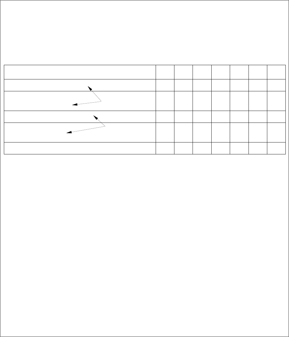
Requirements/Location 1234567
Nozzle "316 X X
Extern. optical centering
Head camera
222
6666
Transport direction left X X X X
Feeder "S_LIN_30"
Feeder "S_G_24N" X X
XXXX
Tracks still available 90 6 1 120 0 120 120
requirement through the
GF description
requirement through the
restrictions (.ri/.rs)
11 Production Tools / Optimization User Manual Line Computer UNIX
11.3 Setup Optimization Software Version 501.xx 01/99 Issue
11 - 18
Example for the determination of error causes by means of the error display:
1. The component cannot be set up at feeder location 6 or 7 since nozzle „316“ is not available at these
feeder locations.
2. The two resources 'External optical centering station' and 'Head camera' do not result in any further
restriction since centering can be performed with either resource available.
3. Locations 1, 4 and 6 are not available owing to the user-defined restriction 'direction of transport: left'
(see Chapter 9). Thus, in conjunction with item "1.", only feeder locations 2, 3 and 5 remain available
as possible locations.
4. Based on the pre-determined feeder allocation, the component can be set up at any location with the
exception of location 3. The possible feeder is set up by the optimization program. In conjunction with
items "1." and "3.", the component can thus be set up at feeder location 2 or 5.
5. At the time the error message was released, 6 tracks were still available at location 2, whereas location
5 was already completely occupied. Since feeder S_G_24N (24mm tape) requires 9 tracks, also location
2 is occupied and thus no longer available for this component.
Result:
Locations 2 and 5 that were possible locations for the setup of component "YZ", are overloaded and are
thus no longer available for the component.
The error file was created to facilitate analysis of the causes.
Possibilities of Error Correction:
1. Making the resources required for this component "YX" also available at other locations, e.g. by
allowing nozzle 316 to be set up at locations 6 and/or 7.
2. Cancelling the binding of the component to one side (restriction: direction of travel, left) so that it can
be set up on either side of the line.
3. Removing technical or user-defined restrictions of other components which, at present, can also only
be set up at locations 2 and/or 5 in order to relieve these locations.
4. Increasing the available space at locations 2 and/or 5, if space is limited owing to machine components
already set up.

User Manual Line Computer UNIX 11 Production Tools / Optimization
Software Version 501.xx 01/99 Issue 11.4 Optimization Dialog
11 - 19
11.4 Optimization Dialog
The Optimization Dialog is the user interface of the Set-Up Optimization. Via the Optimization Dialog it is possible
to create lot files, start the optimization process and display the results of the optimization runs. Moreover, all
relevant editors can be invoked from the Optimization Dialog.
11.4.1 Starting the Optimization Dialog
The Optimization Dialog is called up from the desktop:
In the programming mode:
● Click on icon „Optimization“.
The Optimization Dialog is opened.
NOTE
If the "Clustering" option is installed, the "Optimization" icon will be displayed
as follows:
In the control mode:
● On the „PRODUCTION TOOLS“ desktop menu click on the „Optimization“ menu option.
The Optimization Dialog is opened.