00191413-01.pdf - 第149页
User Manual Line Computer UNIX 4 Data Management Software Version 501.xx 01/99 Issue 4.6 CAD Import 4 - 39 4.6 CAD Im port Extern ally crea ted pla cement fi les (e.g. fi les cr eated o n CAD system s, PP S syst ems, in …
4 Data Management User Manual Line Computer UNIX
4.5 File Display User Interface Software Version 501.xx 01/99 Issue
4 - 38
4.5.2.2 OPTIONS menu
- Data Type
This menu option enables a filter to be selected from a number of predefined filters which will then
appear in the FSB as the default setting upon selecting "FILE --> Open...".
● Select OPTIONS --> Data type.
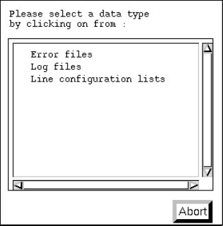
The dialog box containing the listing of the predefined filters is opened.
● Click on desired data type, e.g. Error files (or Abort if the dialog box is to be closed without
selecting a filter).
The dialog box is closed.
- Printer Selectionl
This menu items enables an installed printer to be selected.
● Select OPTIONS --> Printer selection.
The window for the printer selection is opened.
● Select desired printer type and confirm the selection with OK.
- Saving State
This menu item enables the data type and printer selected under Options to be saved so that these
presettings will be available immediately when the File Display is restarted.
● Click on OPTIONS --> Save state.
The currently set options for the data type and the printer selection are saved as default
settings.
User Manual Line Computer UNIX 4 Data Management
Software Version 501.xx 01/99 Issue 4.6 CAD Import
4 - 39
4.6 CAD Import
Externally created placement files (e.g. files created on CAD systems, PPS systems, in databases, etc.) can
be easily adapted to the SIPLACE format with the aid of the user interface of the „CAD Import“ program.
The "CAD Import" program makes a distinction between two modes:
-
Conversion mode
(default mode)
Filters are used as the basis for the data import in the
Conversion mode
.
-
Filter editing mode
The filters required for the determination of the required placement data from the files to be converted,
can be created or modified in the
Filter editing mode
.
When converting the placement data, a cluster size is calculated from the placement positions located at the
outermost positions. This cluster size can be changed to its actual size in a separate window of CAD Import.
In addition, the preset coordinate system can also be changed.
To display the PCB structure created from the converted and modified placement data, the graphics function
provided in the user interface of CAD Import is used.
4.6.1 Prerequisites/Preparatory Steps for the Import of Externally
Created Placement Files
- The placement file (CAD data file) must be available in the ASCII format.
- The name of the file must end with the suffix .cad.
- The file must be copied to the Master data/CAD-Bibliothek directory (see section 4.3.4.1).
- Each data line of a placement position must minimally contain the following PP data:
the component name,
the x and y-coordinates
the placement angle
4 Data Management User Manual Line Computer UNIX
4.6 CAD Import Software Version 501.xx 01/99 Issue
4 - 40
4.6.2 Starting CAD Import
Depending on the operating mode selected, the user interface of CAD Import can be opened either by selecting
the CAD import option from the "PRODUCT" menu on the desktop, or by clicking on the CAD import icon in
the "Products" area.
Moreover, the user interface of CAD Import can also be opened via the Data Manager by clicking on a file with
the suffix .cad in the Master data/CAD-Bibliothek directory.
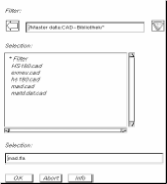
● Click on the CAD import icon on the desktop (or the "CAD import" menu item on the "PRODUCT"
menu). The FSB containing a listing of all available ".cad" files opens.
● Select the "xxx.cad" name of the desired file by double-clicking.
The main window of CAD Import (see Fig. 4.6.1) opens.
The content of the selected file is displayed in the display area.
The name of the filter that was used most recently is entered above the display area,
adjacent to the filter selection button.