00191413-01.pdf - 第245页
User Manual Line Computer UNIX 8 Product / PCB Software Version 501.xx 01/99 Issue 8.1 PCB Editor 8 - 7 8.1.3 Main Display Window of Structure Editor In the foll owing, the secti ons of the main display window and their …
8 Product / PCB User Manual Line Computer UNIX
8.1 PCB Editor Software Version 501.xx 01/99 Issue
8 - 6
8.1.2 Starting the PCB Editor
- In the "programming mode" the PCB Editor is activated by clicking on the PCB icon on the desktop or
via the Data Manager (see chapt. 4).
- If the LC program was installed for the "control mode", the PCB Editor can be started via the
"PRODUCT" menu on the desktop, or via the Data Manager.
● Click on the PCB icon on the desktop (or the "PCB Editor" option on the "PRODUCT" menu).
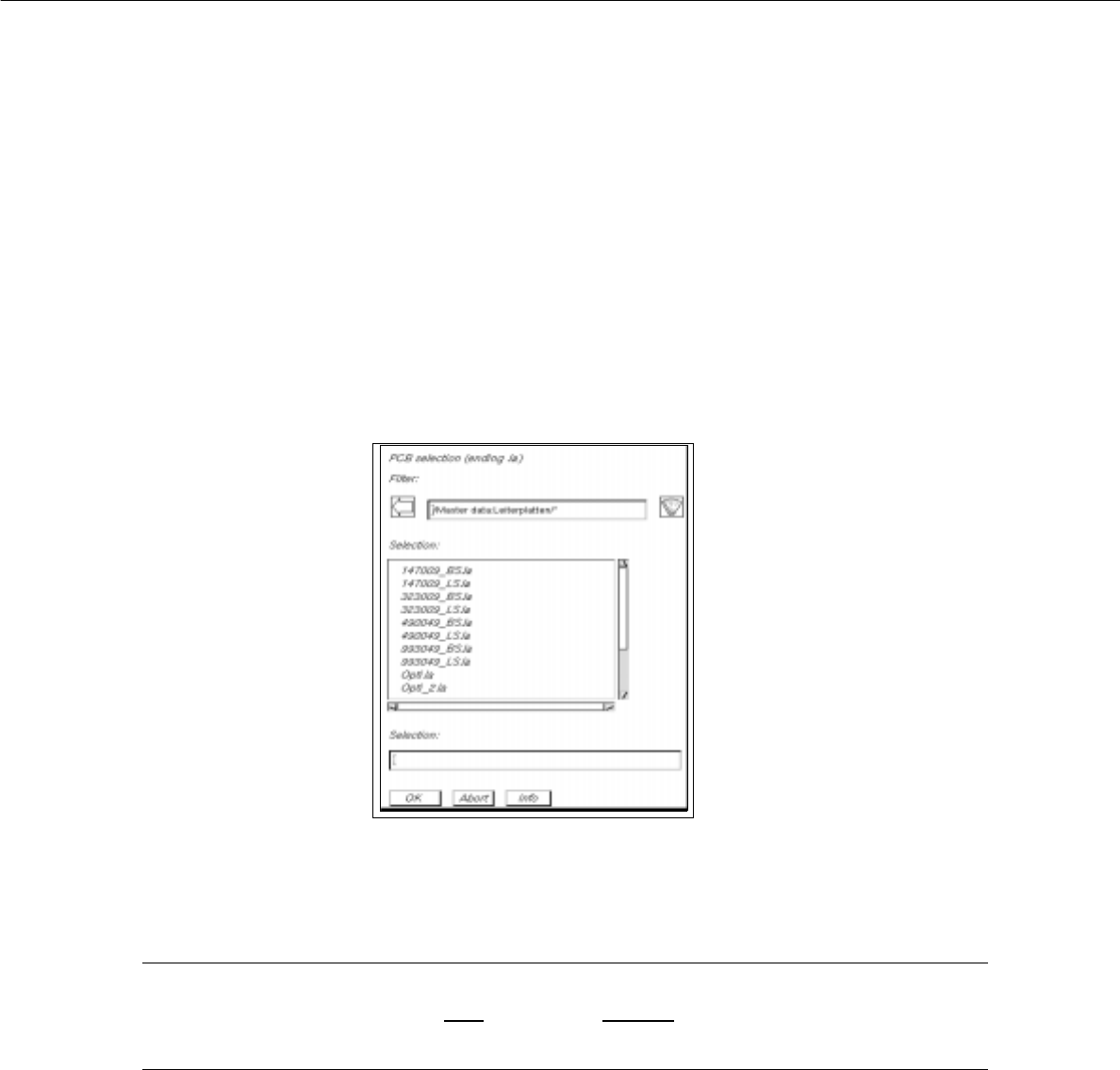
The FSB containing the files of all already-defined PCBs is opened.
● Select name "xxx.la" of the PCB desired by double-clicking, or enter the new number using the
keyboard and confirm with OK.
The main window of the PCB Editor, the so-called Structure Editor (see Fig. 8.1.4), is opened.
NOTE
The name of the PCB may comprise max.
20 characters including the suffix ".la". Some characters
must not be used for the name, see chapt. 2, section 2.3 in this connection.
User Manual Line Computer UNIX 8 Product / PCB
Software Version 501.xx 01/99 Issue 8.1 PCB Editor
8 - 7
8.1.3 Main Display Window of Structure Editor
In the following, the sections of the main display window and their functions are described.
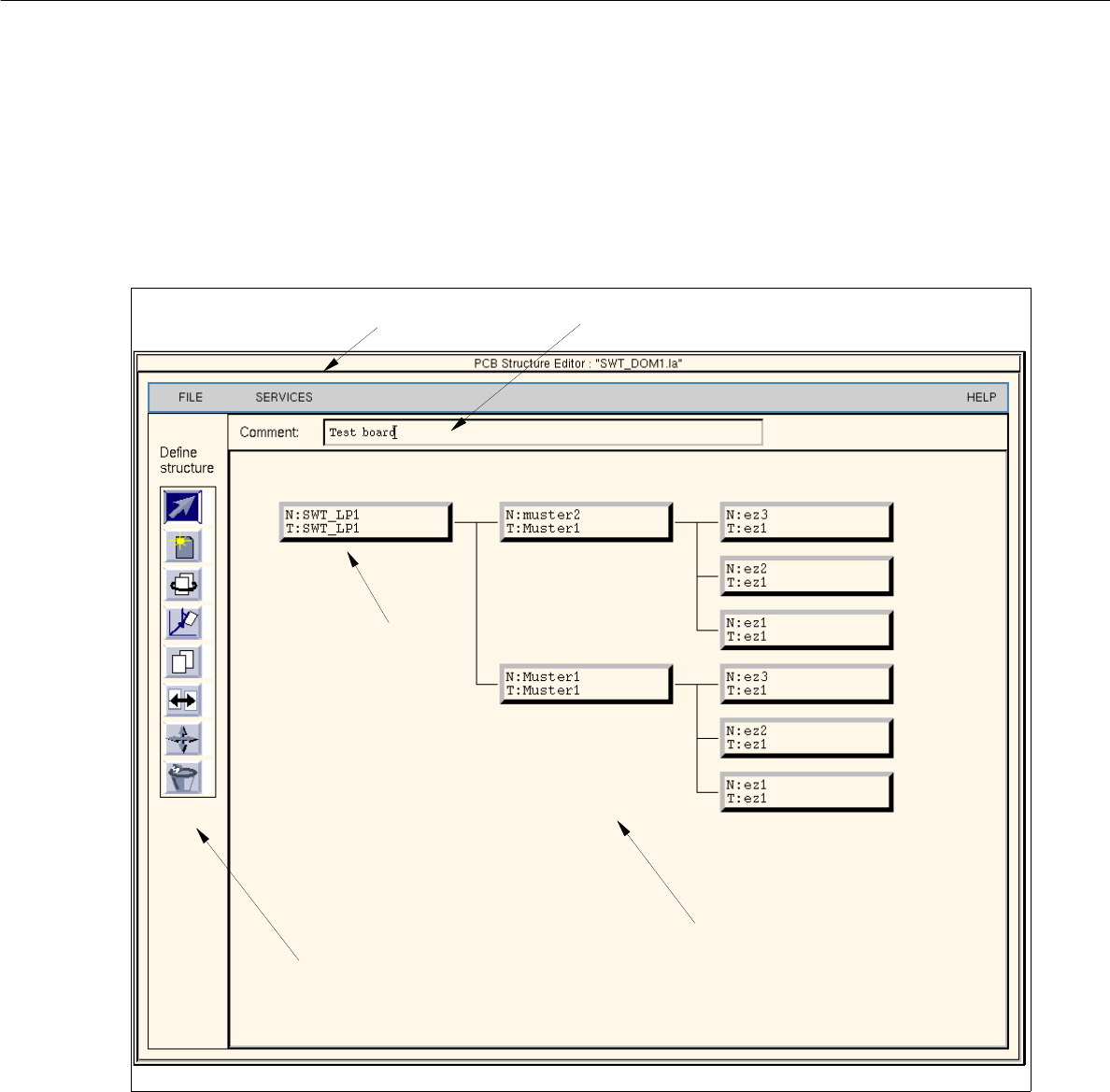
Fig. 8.1.4 Main window "PCB Structure Editor" (Display Structure Mode)
The main display window is subdivided as follows:
- Menu
- Editing field
- Display Area
- Command Area (only available in the structure mode)
- Setting Area (only available in the graphic mode, Fig. 8.1.6)
menu bar
display area
command area
uppermost partial
PCB structure
editing field

8 Product / PCB User Manual Line Computer UNIX
8.1 PCB Editor Software Version 501.xx 01/99 Issue
8 - 8
Menu bar
The menu bar contains the "FILE", "SERVICES" and "HELP" menus.
The functions of the "Open..." and "Copy PCB" menu options of the "FILE" menu are explained in more detail
in section 8.1.3.1. A complete description of the "SERVICES" menu is contained in section 8.1.3.2.
NOTE
Since the functions and operation of the "FILE" and "HELP" menus are similar to those in other application
programs of the line computer, they are described comprehensively in chapt. 2.
Editing field
In the editing field below the menu bar it is possible to enter a comment. Max. 65 characters may be entered.
(No inverted commas or quotation marks will be accepted.)
Display area
In the display area the selected PCB can be displayed in two different ways, depending on the currently active
"mode":
- Upon opening, the editor is initially in the
"Structure Mode"
(see Fig. 8.1.4). In this mode, the name and the
structure of the loaded PCB are displayed. To be able to manipulate the PCB´s structure, the individual
partial PCB structures must be selected by clicking with the mouse.
- If the editor is in the
"Graphic Mode"
(see Fig. 8.1.6) the entire PCB (depending on the selection of the ele-
ments, see section 8.1.3.4) is displayed graphically, including all placement positions, fiducials, ink spots,
coordinate systems, etc. If the offset values of at least one substructure are not completely defined, a
"structure graphic" is displayed in addition to the display of the PCB (see Fig. 8.1.7).
Command Area
Every command in this area is symbolized by an icon. If a partial PCB structure has been selected in the display
area, it can be manipulated by means of the activated command (see section 8.1.3.3).
Setting area
If the Structure Editor is in the Graphic Mode (see Fig. 8.1.6), different display options can be set using the
selection possibilities offered in this area (see section 8.1.3.4).