00191413-01.pdf - 第250页
8 Product / PCB User Manual Line Computer UNIX 8.1 PCB Editor Software Version 501.xx 01/99 Issue 8 - 12 - Selection If this ic on is activ e (displaye d in reverse video, with t he arrow poi nting fro m the bottom left …
User Manual Line Computer UNIX 8 Product / PCB
Software Version 501.xx 01/99 Issue 8.1 PCB Editor
8 - 11
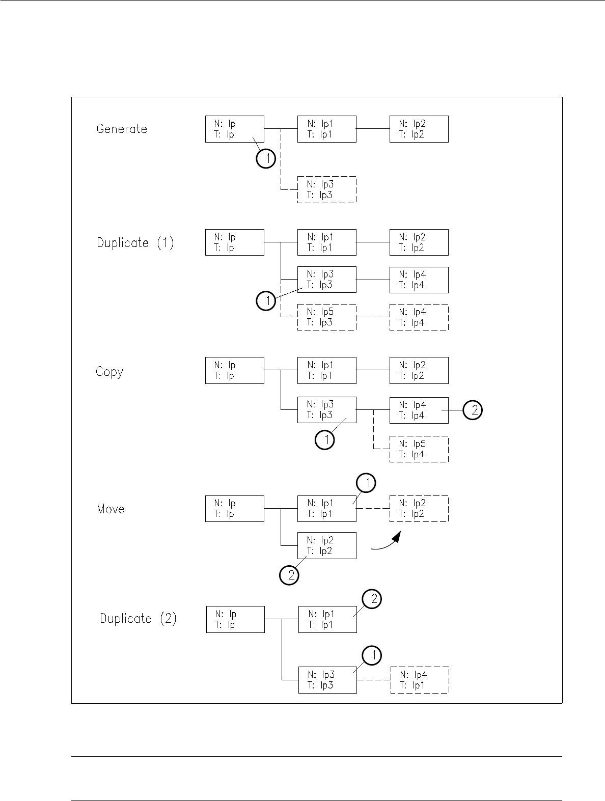
Fig. 8.1.5 Examples "Usage and Results of some Commands in the Structure Editor"
NOTE pertaining to Fig. 8.1.5
"Duplicating (1)" is described on page 8 - 12 and "Duplicating (2)" on page 8 - 14.
8 Product / PCB User Manual Line Computer UNIX
8.1 PCB Editor Software Version 501.xx 01/99 Issue
8 - 12
- Selection
If this icon is active (displayed in reverse video, with the arrow pointing from the bottom left to the top
right), the PP or NU-Editor can be called up for the selected partial PCB structure. If the topmost par-
tial PCB structure is selected, the current PCB can be duplicated using the "Copy PCB" menu
function.
● Activate icon .
● The partial structure selected is highlighted in light green. All partial structures linked to it are
highlighted in dark green.
● Select desired menu function (e.g. SERVICES --> NU-Editor...).
- Generating a new partial PCB structure with the corresponding new PCB type
This command serves to generate a new partial structure with a cross-reference to a new PCB type.
● Activate icon .
● Select PCB type.
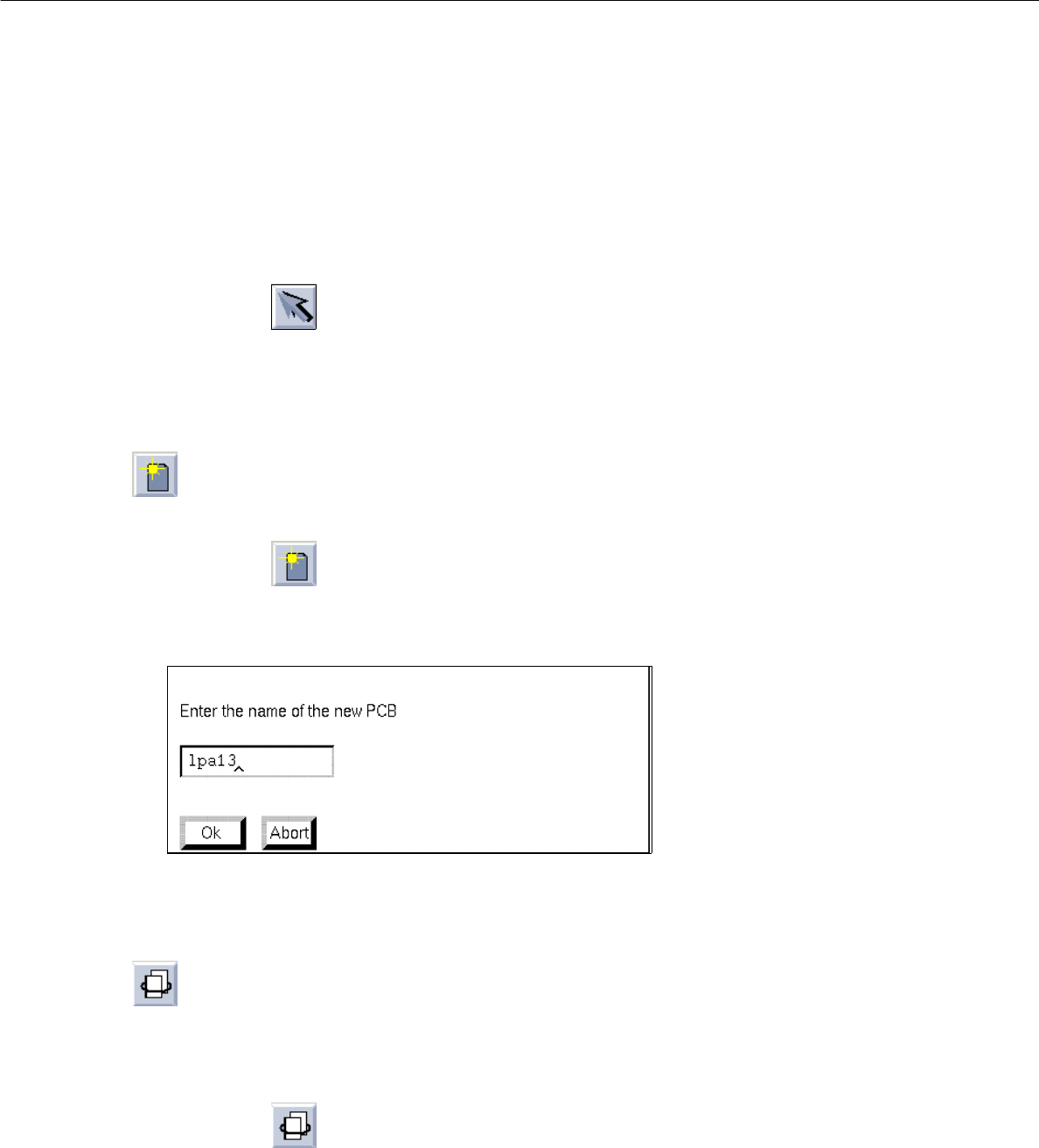
The following dialog box for entering the name is displayed.
● Enter the name and confirm with OK.
The new PCB type is appended to the selected one and displayed in the display area.
- Duplicating a partial PCB structure
Existing cross-references to a given PCB type can be duplicated from a PCB partial structure thus
generating a new partial structure. Except for the coordinates, the data of the duplicated partial PCB
structure are identical.
● Activate icon .
● Select partial PCB structure.
The dialog box for entering the name is displayed.
● Enter the name and confirm with OK.
User Manual Line Computer UNIX 8 Product / PCB
Software Version 501.xx 01/99 Issue 8.1 PCB Editor
8 - 13
- Setting cluster offset
For each
partial structure a cluster offset must be entered. By entering the cluster offset the PCB type
is provided with a coordinate offset, and a partial PCB structure is thus completely described.
● Activate icon .
● To define the position of the board (complete cluster) in the machine, first click on the uppermost
partial PCB structure of the PCB structure.
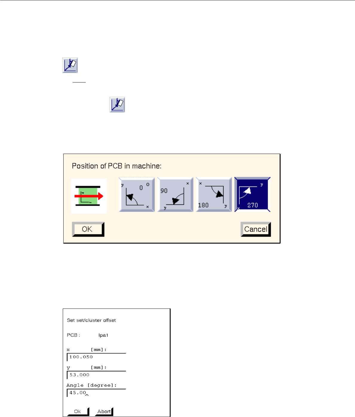
The following dialog box appears:
● Select position by clicking on 0°, 90°, 180° or 270° in the dialog box.
● Confirm with OK.
● Click on partial PCB structure of the PCB structure.
The following dialog box appears:
● Enter x, y-coordinates and angle with respect to partial PCB structure (cluster) in which the selec-
ted lower partial structure is contained (see Fig. 8.1.2).
● Confirm with OK.
● Repeat procedure for all partial PCB structures existing in the partial PCB structures loaded.