00191413-01.pdf - 第189页
User Manual Line Computer UNIX 6 Product / Package Form Software Version 501.xx 01/99 Issue 6.1 Package Form Editor 6 - 11 6.1. 2.4 Package Form Editor Command Area - "Visi on data" Screen NOTE The comma nd are…

6 Product / Package Form User Manual Line Computer UNIX
6.1 Package Form Editor Software Version 501.xx 01/99 Issue
6 - 10
6.1.2.3 Selection Field "Features" (PDC) - "Vision data" Screen
-
Cubic component
The characteristic of the current package form can be set by means of the "Cubic component" button.
By default, this button is automatically activated when the Package Form Editor is opened. This set-
ting means that the current package form is of cubic design (featuring a plane top) permitting the
vision system to expect clearly outlined borders.
The setting "Cubic component" must be deactivated by clicking on the button whenever a cylindrical
package form is present.
If the component is to be picked up off-center (in relation to the package form’s center) for subsequent
placement, the setting "Cubic component" must be deactivated as well.
NOTE
If the current package form is a standard package form, the setting under Properties cannot be chan-
ged since the button is inactive.
In the case of FDCs and BGAs the "Cubic component" button is contained in the "Acceptance limits"
editing area.
User Manual Line Computer UNIX 6 Product / Package Form
Software Version 501.xx 01/99 Issue 6.1 Package Form Editor
6 - 11
6.1.2.4 Package Form Editor Command Area - "Vision data" Screen
NOTE
The command area is not displayed if the current package form is of the "PDC" type (see Fig. 6.1.2).
In the command area (see Fig. 6.1.1) only the "Create" command can initially be selected. The remaining
commands cannot be activated until an already-created pin or grid group is selected from the view area.
COMMANDS
The procedures for executing the commands are described in the following.
-
Create
A new pin group (see section 6.1.3.2) or a new grid group (see section 6.1.3.3) can be created.
●
Click on Create.
The window for the description of the new pin or grid group is opened (see Fig. 6.1.20 and
Fig. 6.1.25).
-
Delete
A selected pin or grid group can be deleted.
●
In the view area, select any pin or ball of the group you wish to delete. The selected group is
displayed, surrounded by a rectangle.
●
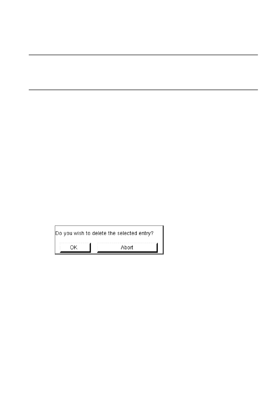
Click on Delete.
The following dialog box is opened.
●
Click on OK in the dialog box.
The dialog box is closed. The group is no longer displayed in the view area.
-
Group
This command permits the window for the description of the group data for a selected object (pin
group/grid group) to be opened.
●
From the view area select the group whose group data you wish to edit.
The selected group is surrounded by a rectangle.
●
Click on Group.
The window for the description of the group data is displayed on the screen (see Fig. 6.1.20 or
Fig. 6.1.25).

6 Product / Package Form User Manual Line Computer UNIX
6.1 Package Form Editor Software Version 501.xx 01/99 Issue
6 - 12
-
Pin/Ball
This command permits the window for the description of the model data for a selected object
(pin/ball) to be opened.
●
From the view area select the group containing the object (pin/ball) whose model data you wish to
edit.
The selected group is surrounded by a rectangle.
●
Click on
Pin/Ball
.
The window for the description of the model data is displayed on the screen (see Fig. 6.1.21 or
Fig. 6.1.26).
6.1.2.5 Package Form Editor Editing Fields - "Vision data" Screen
NOTE
When an existing GF-file is opened upon the start-up of the Package Form Editor, the factory or customer
defined default values are contained in the editing fields described below.
Editing field "Nominal dimensions"
-
X +/-
[mm] component length, with indication of the tolerances
see Fig. 6.1.18 or Fig. 6.1.23
-
Y +/-
[mm] component width, with indication of the tolerances
see Fig. 6.1.18 or Fig. 6.1.23
-
Z +/-
[mm] component height, with indication of the tolerances
see Fig. 6.1.19 or Fig. 6.1.23
NOTE
The length of a component refers to the x-direction and its width to the y-direction.
The value for the nominal dimension "Z" (height) is used to calculate the travel path of the z-axis during
picking up and placing the component as well as during centering above the IC- or flip-chip camera. Any
incorrectly entered value can therefore result in errors in processing the component. Normally, the value
entered for "Z" refers to the dimension measured from the top side (= contact area of nozzle) to the bottom
side of the package form. However, in the case of package forms (e.g. headers) featuring an indentation
in the center, care must be taken to enter for "Z" the dimension measured from the indented
area to the
bottom side (see Fig. 6.1.6).