00191413-01.pdf - 第184页
6 Product / Package Form User Manu al Line Computer UNIX 6.1 Package Form Editor Software Version 501.xx 01/99 Issue 6 - 6 Fig. 6.1. 5 Main Window "Package Form Editor (Displaying Handling Data - I rregular FDC)&quo…
User Manual Line Computer UNIX 6 Product / Package Form
Software Version 501.xx 01/99 Issue 6.1 Package Form Editor
6 - 5
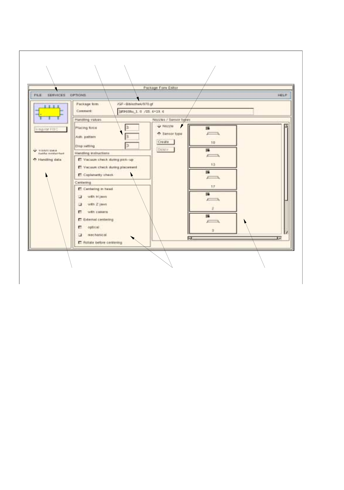
Fig. 6.1.4 Main Window "Package Form Editor (Displaying Handling Data - Irregular FDC)"
selection fields
menu bar command area
area for general settings
selected nozzle title bar
editing area
view area
(nozzles)
6 Product / Package Form User Manual Line Computer UNIX
6.1 Package Form Editor Software Version 501.xx 01/99 Issue
6 - 6
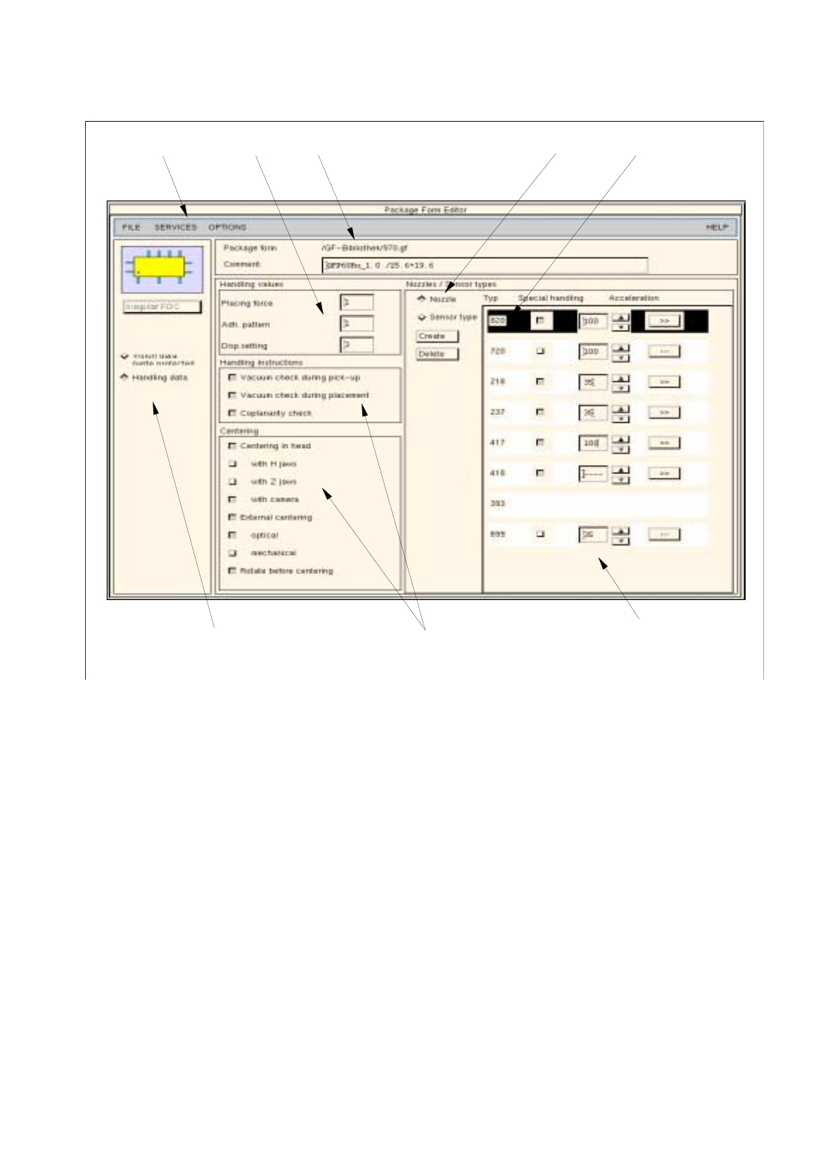
Fig. 6.1.5 Main Window "Package Form Editor (Displaying Handling Data - Irregular FDC)"
The areas of the main window and their functions are explained in the following.
The main window of the Package Form Editor (displaying "Vision data" or "Handling data") is subdivided as
follows:
-
Title bar
-
Menu bar
-
Area for general settings
-
Selection fields
-
Command area
-
Editing area
-
View area
selection fields
menu bar title barediting area
view area
command area
(sensor types)
area for general settings

User Manual Line Computer UNIX 6 Product / Package Form
Software Version 501.xx 01/99 Issue 6.1 Package Form Editor
6 - 7
Title bar
The title bar displays the directory in which the selected package form (or the GF-file) is contained, and the
number of the package form.
In the editing field below the title bar it is possible to enter a comment, e.g. the package form assigned to the
GF-no. (No inverted commas or quotation marks will be accepted. Max. 255 characters may be entered.)
The comment can be modified at any time, i.e. even after the package form has been saved.
Menu bar
The menu bar contains the "FILE", "SERVICES", "OPTIONS" and "HELP" menus.
A complete description of the "SERVICES" menu is contained in section 6.1.2.1.
NOTE
Since the functions and operation of the "FILE", "OPTIONS" and "HELP" menus are similar to those in other
application programs of the line computer, they are described comprehensively in chapt. 2.
Area for general settings
The layout of the main window is determined by clicking on the buttons
Vision data
or
Handling data
.
Moreover, with customer-specific package forms it is possible to subsequently change the package form type
(except for the "BGA" type) using the <Package form type> button (see section 6.1.2.2).
Selection fields
(see section 6.1.2.3 and section )
With the setting
Vision data
the characteristics of the current component type can be selected (see section 6.1.2.3).
In the
Handling data
screen, the processing method for the current component type can be defined (see section
6.1.2.10).
Command area
The commands that may have been activated in this area, in combination with the settings
FDC
or
BGA
and
Vision data
, enable pin groups and grid groups to be generated or deleted (see section 6.1.2.4). Moreover,
the window for the description of the model data or group data for a selected object (pin, group, ball, grid group)
can be opened. If setting Handling data has been selected, nozzles and sensor types can be generated or
deleted (see section 6.1.2.7).
Editing areas
(see section 6.1.2.5 and section 6.1.2.11)
If the
Vision data
setting has been selected, the dimensions of a package form (including its tolerances) are
defined by entering values in the respective editing fields of the editing areas. Moreover, the "cubic/non-cubic"
feature can be defined for FDCs and BGAs.
If
Handling data
setting has been selected, the placing force, the number of the adhesive pattern (which has
been defined for the current package form) and the adhesive amount to be dispensed can be entered.
NOTE
If the currently selected package form is a standard package form (number range 1 ... 1499), all handling data
can be changed. In the case of the vision data, only
the values for the packaging tolerances can be edited. All
other vision data are write-protected.