00191413-01.pdf - 第287页
User Manual Line Computer UNIX 9 Production Tools / Feeders Software Version 501.xx 01/99 Issue 9.1 Feeder Editor 9 - 3 Exampl e of a type- specific alloca tion of the co mponent "x xx" with p ackage fo rm &quo…
9 Production Tools / Feeders User Manual Line Computer UNIX
9.1 Feeder Editor Software Version 501.xx 01/99 Issue
9 - 2
9.1.1 Allocation Possibilities
The various possibilities of allocations are described in the following:
For each
package form, and thus each component, contained in the master data it is necessary that its set-up
be defined at one time, i.e. an allocation must be defined between component/package form -> feeder ->
machine type.
NOTE
To limit the amount of work involved, allocations should preferably be made for package forms, as different
components frequently have the same package form.
- The component/package form can be set up on one side of a line only.
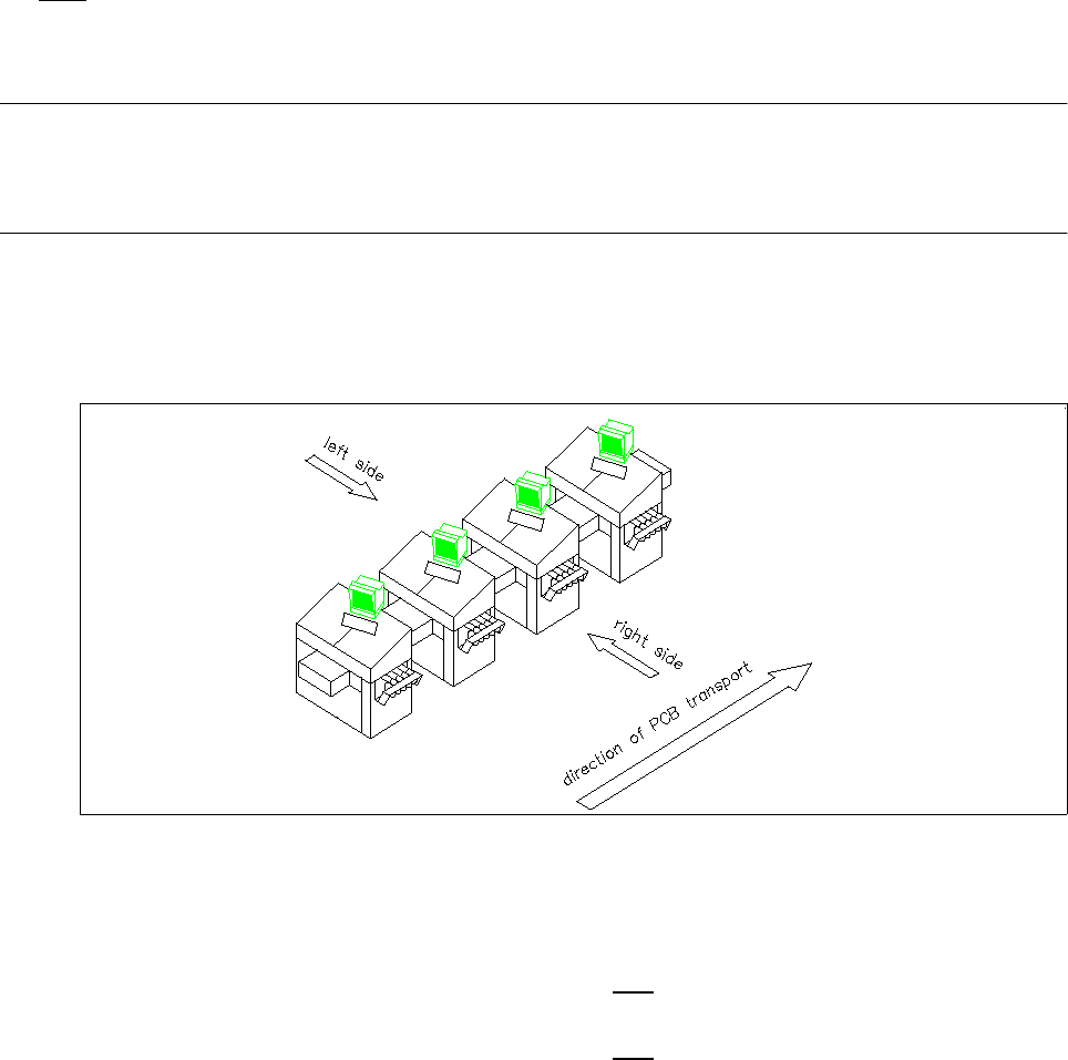
The distinction between the machine sides is accomplished by the designations "Left side" and "Right
side" (as seen in the direction of travel).
Fig. 9.1.1 Direction of travel, left side/right side
The definitions are determined according to the following types of allocation:
Left side ---> The component/package form may
only be set up on the feeder parts of the
left side of the line.
right side ---> The component/package form may
only be set up on the feeder parts of the
right side of the line.
- The component/package form can only be set up on a specific machine type.
- The feeders can be assigned correction values for the pick-up position of a component
(x,y,z and α) as well as the vibration time.

User Manual Line Computer UNIX 9 Production Tools / Feeders
Software Version 501.xx 01/99 Issue 9.1 Feeder Editor
9 - 3
Example of a type-specific allocation of the component "xxx" with package form "541":
Machine type: HS-180
Feeder type: 12mm-tape feeder
Machine type: SIPLACE80S
Feeder type: 9.5mm-linear feeder
Explanation: The optimization process offers the possibility to set up the component "xxx"
either on the machine type "HS-180" or
the machine type "SIPLACE80S"
The machine types "WPC", "SIPLACE80F" and "HS180-HR" are not
mentioned. The component must therefore not be set up on these types.
If the optimization process determines that the component is to be set up on
the machine type "HS-180", the component will be supplied in a 12mm-tape
feeder. If, however, the optimization process determines that the component
is to be set up on the machine type "SIPLACE80S", the component will be
supplied by a 9.5mm-linear feeder.
9.1.2 Starting the Feeder Editor
- In the "programming mode" the Feeder Editor is activated by clicking on the Feeder icon on the
desktop, or via the Data Manager (see chapt. 4).
- If the LC program was installed for the "control mode", the Feeder Editor can be started via the
"PRODUCTION TOOLS" desktop menu, or via the Data Manager.
● Click on the Feeder icon on the desktop (or the "Feeder Editor" option on the "PRODUCTION
TOOLS" menu). The main window of the Feeder Editor is opened (see Fig. 9.1.2).
NOTE
Moreover, the Feeder Editor can be started via the Data Manager user interface by selecting the
".ri" set-up info file in the "Master data/RI-Bibliothek/*" path (see chapt. 4), via the Optimization user
interface (see chapt. 11), or via the Package Form Editor (see chapt. 6).
9 Production Tools / Feeders User Manual Line Computer UNIX
9.1 Feeder Editor Software Version 501.xx 01/99 Issue
9 - 4
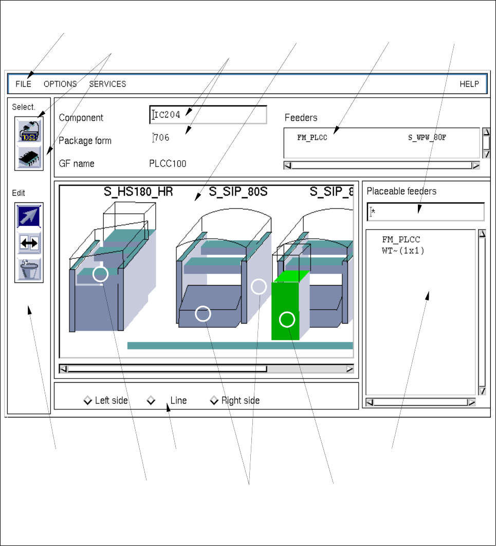
9.1.3 Main Window of the Feeder Editor
In the following, the areas of the main window and their functions are explained.
Fig. 9.1.2 Main Window "Feeder Editor" (Allocation of the Component "IC204" with Package Form "704")
selection field
"Placeable feeders"
setting area
command area
selection:
WPC trolley
(SIPLACE 80F)
selection:
complete
selection:
Feeder part on
the right
machine side
machine type
menu bar editing fields
"Component/
"Package form"
selection field
"Feeder"
filter field
selection area
"Component/
Package form"
display
area