00191413-01.pdf - 第485页
User Manual Line Computer UNIX 14 Control / Control Modules Software Version 501.xx 01/99 Issue 14.4 Set-Up Modification Generator 14 - 49 14.4.4.2 Command Area NOTE The buttons in the command area can not be sel ected i…

14 Control / Control Modules User Manual Line Computer UNIX
14.4 Set-Up Modification Generator Software Version 501.xx 01/99 Issue
14 - 48
14.4.4.1 FILE Menu
- Saving the created follow-up set-up.
NOTE
This menu item can only be selected if a PCB-specific follow-up set-up has been created by the
Set-Up Modification Generator.
● Click on FILE --> Save.
The data are stored in the master data storage.
- Printing the set-up for the stations selected in the selection area "Stations" (corresponds to the
current display) or the set-up for all stations of the line
● Select FILE --> Print --> Print Station or FILE --> Print --> Print Line.
The data are output to the connected printer.
- Iconifying the Set-Up Modification Generator
NOTE
This menu item cannot
be selected when the Set-Up Modification Generator was opened automati-
cally by a station controller (initiated by a requesting program).
● Select FILE --> Iconify.
The Set-Up Modification Generator is reduced to an icon on the desktop, it is, however, still
active. Upon clicking on the icon, the main window of the Set-Up Modification Generator is
redisplayed.
- Quitting the Set-Up Modification Generator
NOTE
This menu item cannot
be selected when the Set-Up Modification Generator was opened automati-
cally by a station controller (initiated by a requesting program). In this case, when exiting from the
Set-Up Modification Generator, the note on page 14 - 51 is to be observed.
● Select menu item FILE --> Quit.
The main window is closed. The Set-Up Modification Generator is reduced to an icon on the
desktop.

User Manual Line Computer UNIX 14 Control / Control Modules
Software Version 501.xx 01/99 Issue 14.4 Set-Up Modification Generator
14 - 49
14.4.4.2 Command Area
NOTE
The buttons in the command area cannot
be selected if Set-up or PCB-specific part of set-up has been
selected in the selection window.
In the following, the functions of the commands and the procedure for the execution of the commands are
explained with the "Siplace_2" station serving as an example:
- Viewing the initial set-up of the "Siplace_2" station
● From the selection field "Sublines" select the subline containing the desired "Siplace_2" station.
● Select station Siplace_2 from the "Stations" selection field.
● Click on button Initial set-up. The initial set-up for station "Siplace_2" is displayed in the display
area.
Only in cases where the changeover request originated from the station controller or the Data
Manager is this the current set-up, or when the operator has made his selection in the selection
window based on the current set-up.
- Viewing the follow-up set-up for the "Siplace_2" station
● Click on button Follow-up set-up.
The follow-up set-up for the "Siplace_2" station that was initíally selected from the FSB or created
by the Set-Up Modification Generator (see section 14.4.3.2) displayed.
- Viewing the Target set-up for a station
● Click on button Target set-up.
The target set-up for the "Siplace_2" station initially selected from the FSB (see section 14.4.3.2)
is displayed.
NOTE
The button Target set-up" can only be selected when Current set-up --> PCB-specific set-up or
Set-up --> PCB-specific set-up has been selected from the selection window, i.e. changeover
instructions for the production of a specific PCB type are to be generated.
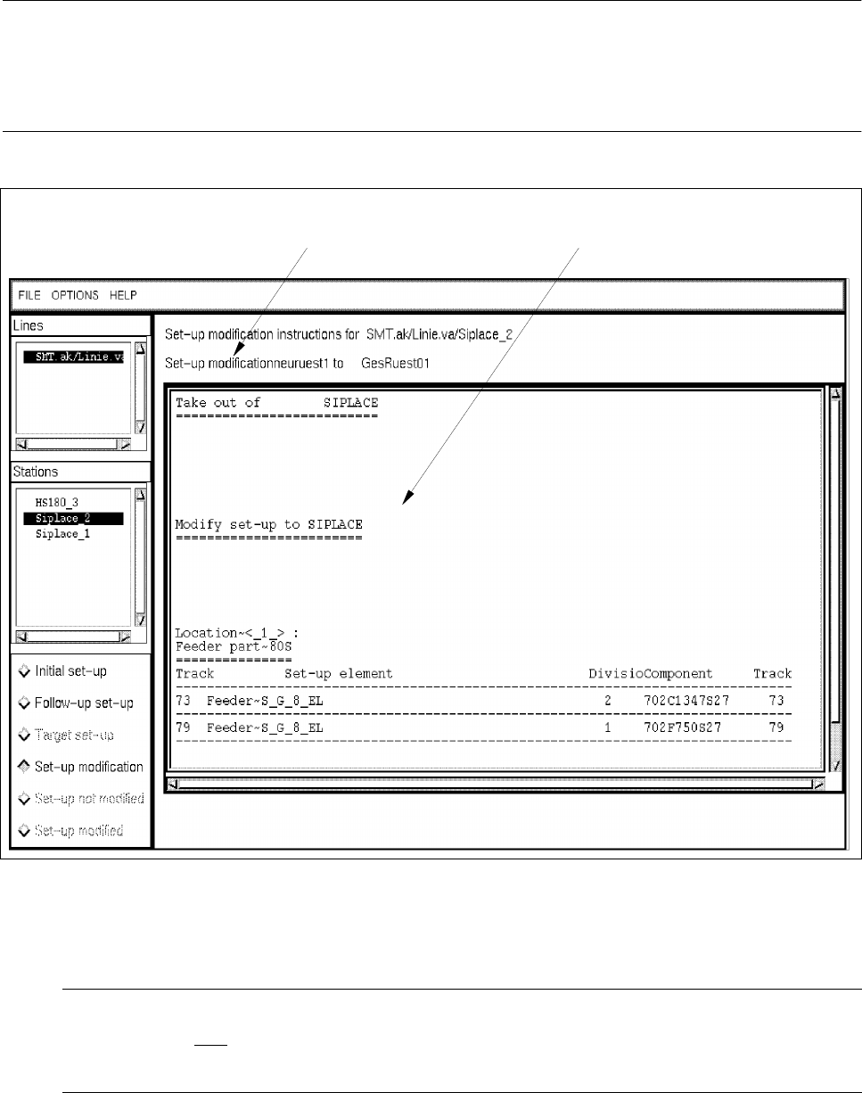
- Creating and viewing changeover instructions (Set-up modification) (see Fig. 14.4.3)
● Click on button Set-up modification.
Depending on the set-up changeover selection made from the selection window (see
Fig. 14.4.1), instructions for changeover - created by the Set-Up Modification Generator - from the
initial set-up to the selected set-up or a follow-up set-up created by the Set-Up Modification Gene-
rator (see section 14.4.3.2) are displayed for the "Siplace_2" station.
When the Set-Up Modification Generator was opened by a station controller, changeover instruc-
tions for the changeover from the current set-up on the station to the follow-up set-up are created
and displayed.
14 Control / Control Modules User Manual Line Computer UNIX
14.4 Set-Up Modification Generator Software Version 501.xx 01/99 Issue
14 - 50
NOTE
If during the creation of changeover instructions for a PCB-specific set-up one realizes that certain set-up
elements (e.g. components) are missing in the selected target set-up, an error message is displayed for each
of the missing elements.
Fig. 14.4.3 Display of Changeover Instructions for the Station "SIPLACE_2"
- Set-up not modified
NOTE
This button can only
be selected when the Set-Up Modification Generator was opened by a station
controller (initiated by a requesting program).
The operator clicks on this button when he was not able to physically modify the selected station for
any reason.
message line display area