FlexTRAK OH Material Handler Manual.pdf - 第103页
FlexTRAK-OH Material Handli ng System IOM Manual Material Handler Operation © 2023 Nordson C orporation 4-15 4.9.8 Conversi on Kit RFID Tag Select CONVERSION KIT TAG from the Control screen ( Figure 4-9 ) to open the RFI…
FlexTRAK-OH Material Handling System IOM Manual Material Handler Operation
4-14 © 2023 Nordson Corporation
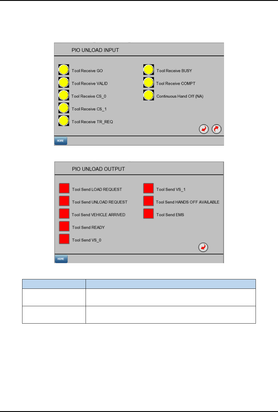
4.9.7 PIO Unload Input/Output
Select UNLOAD PIO IO from the Control screen (Figure 4-9) to open the PIO Unload Input and PIO
Unload Output screens (Figure 4-16).
PIO Unload Input
PIO Unload Output
Label
Description
PIO Unload Input
Yellow: PLC not receiving signal from PIO Unload.
Green: PLC received signal from PIO Unload.
PIO Unload Output
Red: PLC is not sending signal to PIO Unload.
Green: PLC is sending signal to PIO Unload.
Figure 4-16 PIO Unload Input/Output Screens
FlexTRAK-OH Material Handling System IOM Manual Material Handler Operation
© 2023 Nordson Corporation 4-15
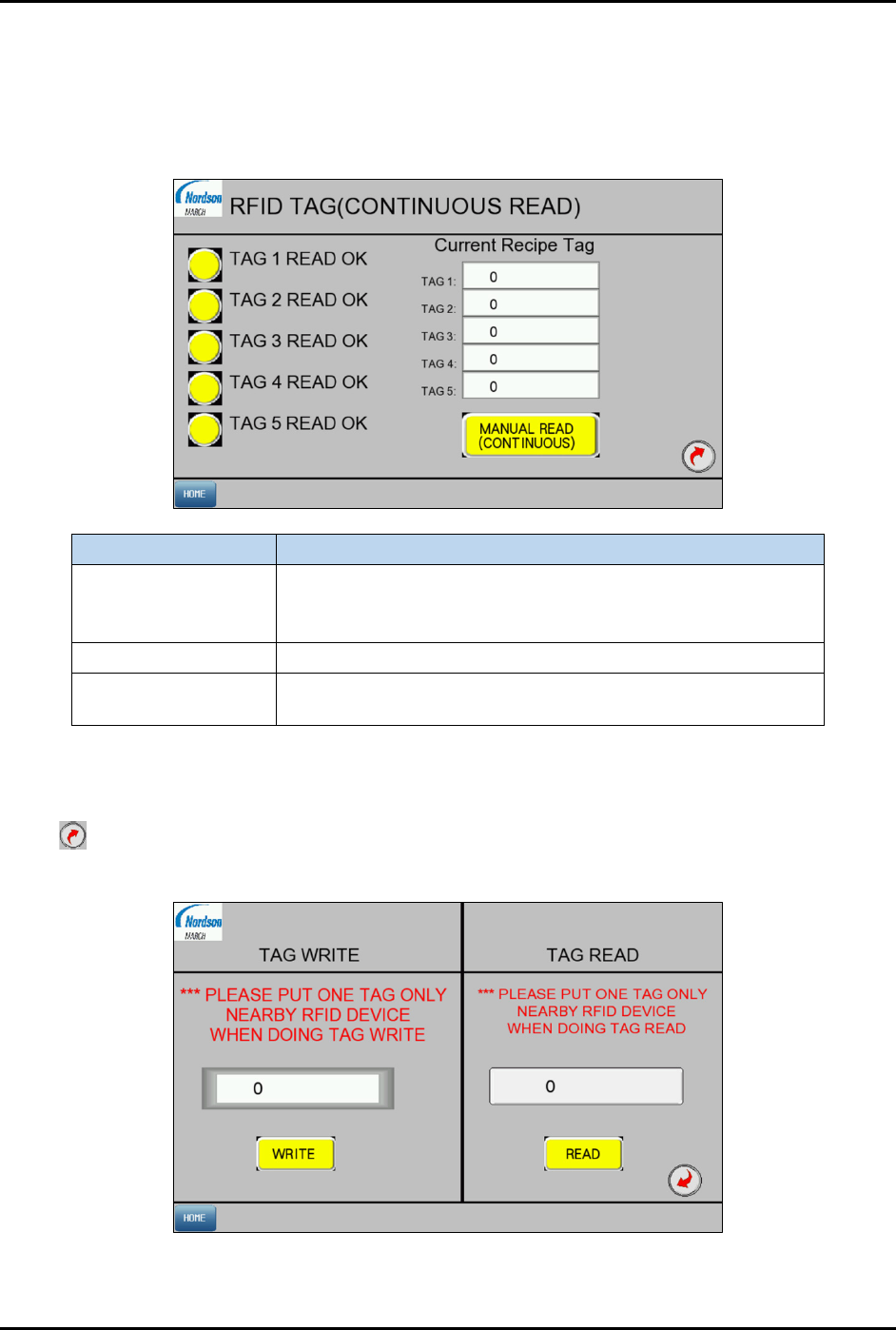
4.9.8 Conversion Kit RFID Tag
Select CONVERSION KIT TAG from the Control screen (Figure 4-9) to open the RFID Tag screen
(Figure 4-17).
4.9.8.1 RFID Tag Screen 1
Label
Description
Tag # READ OK
Yellow: TAG # does not match the saved Recipe Tag ID.
Green: TAG # is verified by the reader to match the saved
Recipe Tag ID.
Tag 1 to Tag 5 Shows the list of RFID tag ID that are used in current recipe.
Manual Read
(continuous)
Toggle manual RFID reading for all 5 tags.
Figure 4-17 Conversion Kit Tag Screen 1
4.9.8.2 RFID Tag Screen 2
Select on Screen 1 to access Screen 2. Press WRITE to save the tag ID to the selected recipe for initial
new recipe or conversion kit setup. Press
READ to read the tag ID from RFID tag.
Figure 4-18 Conversion Kit RFID Tag Screen 2
FlexTRAK-OH Material Handling System IOM Manual Material Handler Operation
4-16 © 2023 Nordson Corporation
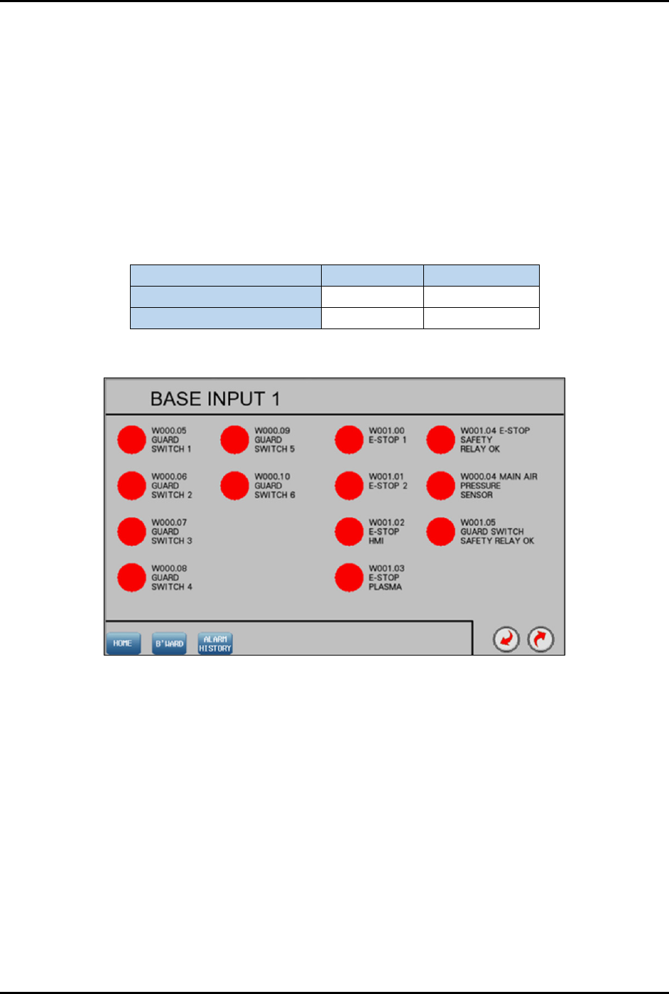
4.10 General I/O Screen
Select General I/O from the Home screen (Figure 4-4) to open the General I/O screen (Figure 4-19). This
screen displays the status of the General Input/Output (I/O) groups for the Material Handler PLC. There
are indicators beside each I/O which turn green or red when that particular input or output is turned ON or
OFF respectively. The I/O status screen is also useful during troubleshooting to check if a sensor is in
good or bad working condition. A red light indicates the I/O is not active and a green light indicates the
I/O is active. Figure 4-19 through Figure 4-22 show the base input and base output screens.
Refer to each electrical wiring cable label shown on the screen to trace the wiring route in the machine
I/O. Table 4-5 shows how to read cable labels from Input and Output screen. The cable description is
similar to the definition stated on the screen.
Table 4-5 Input/Output Cable Labels
Input Cable
Output Cable
Cable label (in interface) W004.00 W024.12
Cable label (in machine) I004.00 O024.12
4.10.1 Base Input 1
Figure 4-19 Base Input 1