FlexTRAK OH Material Handler Manual.pdf - 第107页
FlexTRAK-OH Material Handli ng System IOM Manual Material Handler Operation © 2023 Nordson C orporation 4-19 4.11 Station Main Menu Layout This Station Main Men u screen display s the status of sp ecific station n umber …
FlexTRAK-OH Material Handling System IOM Manual Material Handler Operation
4-18 © 2023 Nordson Corporation
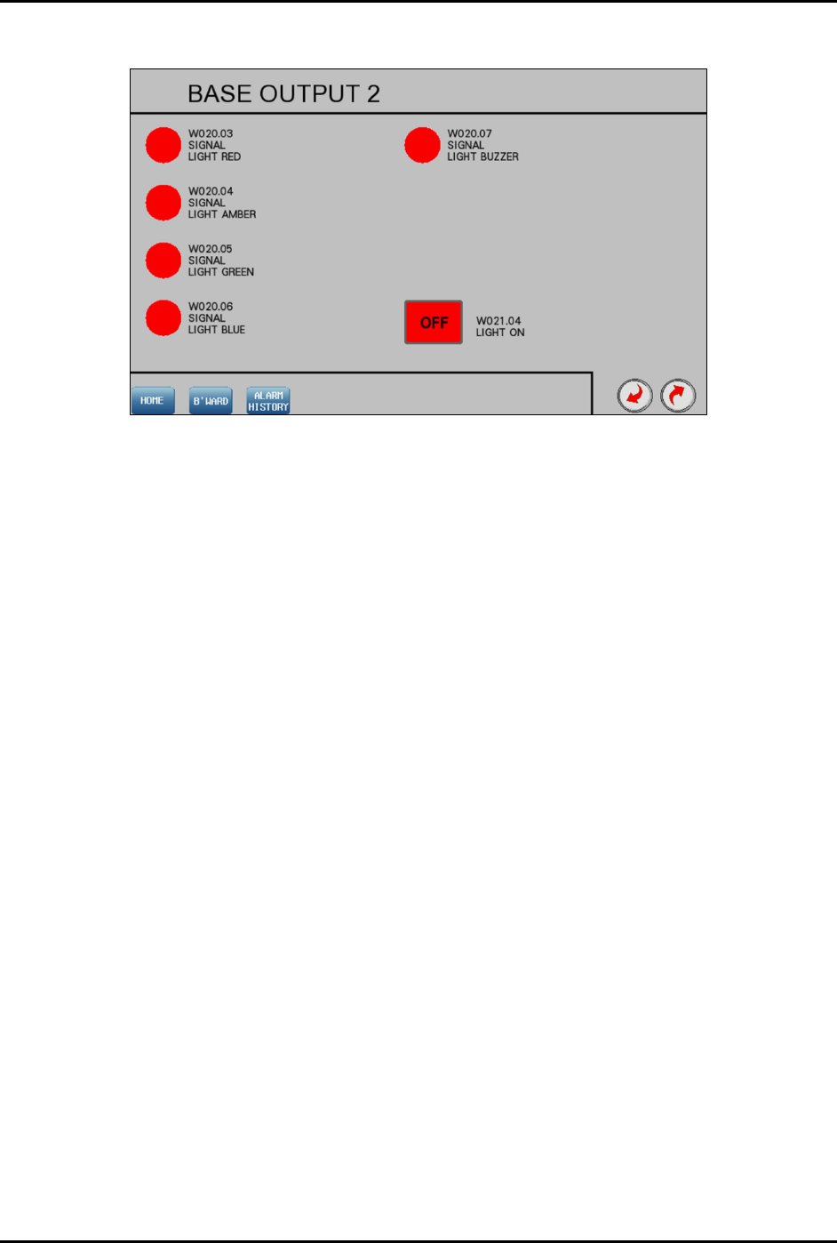
4.10.4 Base Output 2
Figure 4-22 Base Output 2
FlexTRAK-OH Material Handling System IOM Manual Material Handler Operation
© 2023 Nordson Corporation 4-19
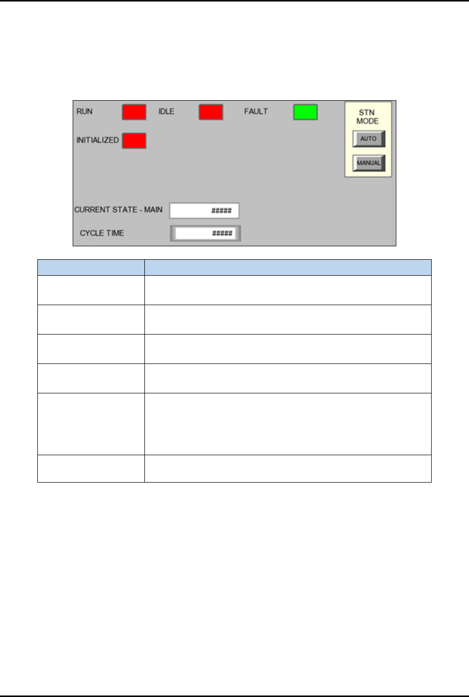
4.11 Station Main Menu Layout
This Station Main Menu screen displays the status of specific station number (#) I/O and device controller
for the Material Handler PLC. The indicators beside each label that turn green or red when that device is
ON/OFF respectively. This screen is also useful during troubleshooting to check if the station device and
sensors are in good or bad working condition.
Label
Description
Run
Red – Station sequence not running.
Green – Station sequence is running.
Idle
Red – Station is not ready to initialize.
Green – Station is ready to initialize.
Fault
Red – Station mechanism has an error.
Green – Station mechanism is good.
Initialized
Red – Station components not initialized.
Green – Station components are initialized.
Current State - Main
Indicates the machine PLC program sequence number been
executed in the current machine station mechanism. This
number value will help the PLC programmer or PLC
administrator during machine or PLC program troubleshooting
task.
Cycle time
Indicates cycle time calculation result for each station to
complete the mechanism sequence.
Figure 4-23 Station Main Menu
FlexTRAK-OH Material Handling System IOM Manual Material Handler Operation
4-20 © 2023 Nordson Corporation
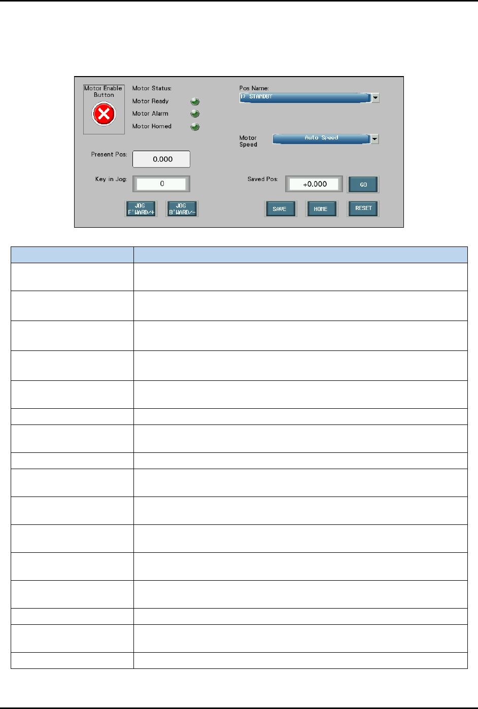
4.12 Motor Interface and Control Switch Settings
Figure 4-24 shows an overview of motor interface and control switch setting screen. This screen is similar
for all stations 10 to 60.
Label Description
Motor Enable Button
Enables (green tick) or disables (red cross) motor actuation task on the
station axis.
Motor Ready
Light green: Motor is ready to be actuated.
Dark green: Motor is not ready to be actuated.
Motor Alarm
Light green: Motor is faulty.
Dark green: Motor is in good condition.
Motor Homed
Light green: Axis flag is at the limit sensor (home position).
Dark green: Axis flag is away from the limit sensor (home position).
Pos Name
Indicates the current motor position name. The drop-down menu will
display the list of available motor axis positions to choose from.
Motor Speed Shows the list of motor actuation speed mode.
Present Pos
Indicates current axis flag position versus the limit sensor (home
position).
Key in Jog The input value for the axis jogging step measurement (in mm).
Saved Pos
Overwrite the previous saved position and replace with the current axis
position name. Then press GO button to start.
Jog Forward/+
Actuates the axis motor to position the axis platform to the machine
front (Y-axis) and left (X-axis) sides.
Jog Backward/-
Actuates the axis motor to position the axis platform to the machine rear
(Y-axis) and right (X-axis) sides.
Jog Upward/+
Actuates the axis motor to position the axis platform to the machine top
side (Z-axis).
Jog Downward/-
Actuates the axis motor to position the axis platform to the machine
bottom side (Z-axis).
Save Save all the motor parameters setup for current selected station.
Home
Actuates the axis motor to position the axis platform to the home
position.
Reset Clears all the motor alarms.
Figure 4-24 Motor Interface and Control Switch Settings