FlexTRAK OH Material Handler Manual.pdf - 第81页
FlexTRAK-OH Material Handli ng System IOM Manual Installation © 2023 Nordson C orporation 3-31 3.7.8 Claw Jam S ensitivit y Adjustme nt To adjust claw jam sensitivity: 1. Prepare a ten sion gau ge ( Figure 3- 53 ) . a. E…
FlexTRAK-OH Material Handling System IOM Manual Installation
3-30 © 2023 Nordson Corporation
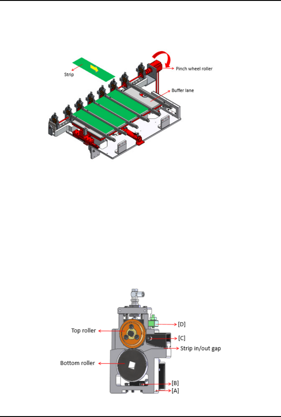
3.7.7.2 Pinch Wheel Gap Adjustment
To verify that the pinch wheel is exerting sufficient pressing force, manually insert a strip and verify that
the strip cannot easily move forward when held back by hand while the pinch wheel rollers are engaged
and in rotation.
Figure 3-51 Inserting a Strip
The gap between the pinch wheel should be adjusted so that the strip is not fully pressed down by the top
roller onto the bottom roller. If the adjustment is done correctly, the top roller will slip or rotate freely if
there is no obstruction to move the strip out to the buffer lane.
To fine-tune the strip in/out gap on pinch wheel (Figure 3-52):
1. Tighten screw (A) to determine pinch wheel contact with LM guide rail.
2. Tighten screw (B).
3. Adjust screw (C) to define the strip in/out gap.
4. Adjust screw (D) to increase or decrease the gap in between top roller and bottom roller,
until all strips are able to move forward or backward by hand with minimum force when the
wheels are engaged.
Figure 3-52 Fine Tuning the Strip In/Out Gap on Pinch Wheel
FlexTRAK-OH Material Handling System IOM Manual Installation
© 2023 Nordson Corporation 3-31
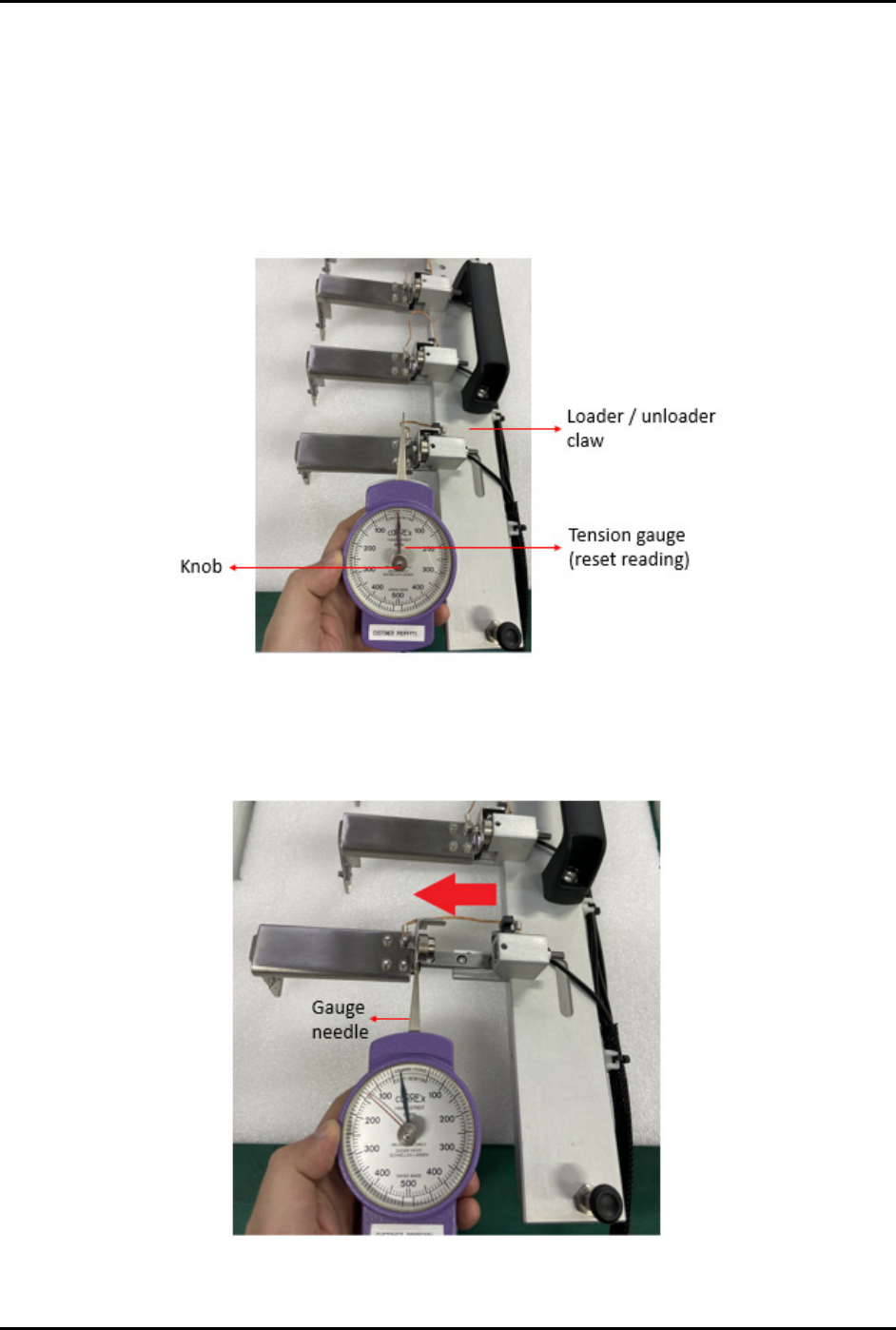
3.7.8 Claw Jam Sensitivity Adjustment
To adjust claw jam sensitivity:
1. Prepare a tension gauge (Figure 3-53).
a. Ensure the tension gauge is in good condition.
b. Reset both needles to the default position by rotating the knob in the clockwise or
counterclockwise direction.
Figure 3-53 Claw Jam Sensitivity Adjustment 1
2. Put the gauge needle on the claw then pull it steadily.
3. Pull the claw jam towards the left side as indicated by the red arrow (Figure 3-54).
Figure 3-54 Claw Jam Sensitivity Adjustment 2
FlexTRAK-OH Material Handling System IOM Manual Installation
3-32 © 2023 Nordson Corporation
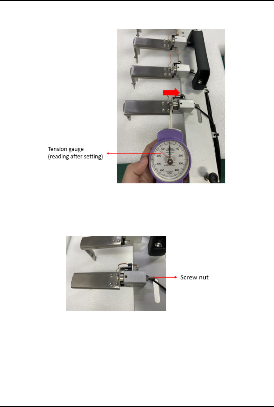
4. Return the claw jam to its original position (Figure 3-55) and then take the reading directly
from the gauge (reading shown by red needle).
Figure 3-55 Claw Jam Sensitivity Adjustment 3
5. If the tension gauge does not show a proper reading, use a screw driver to loosen or tighten
the screw nut (Figure 3-56).
6. Repeat Step 1 through Step 5 until correct reading is obtained.
Figure 3-56 Screw Nut
NOTE The above settings are applicable for both loader and unloader claws. Specification
values are within the range of 80 to 200 grams. Actual settings used should correspond to
maximum allowable force to prevent damage to the strips. Settings should also be
uniform across all buffer lanes. Refer to Table 3-11 for sample readings measured from
each finger.