FlexTRAK OH Material Handler Manual.pdf - 第45页
FlexTRAK-OH Material Handli ng System IOM Manual Safety © 2023 Nordson C orporation 2-15 2.17 Air Preparati on Unit The Air Preparatio n Unit is shown in Figure 2- 13 . Item Part Illustration Function Description/Operati…
FlexTRAK-OH Material Handling System IOM Manual Safety
2-14 © 2023 Nordson Corporation
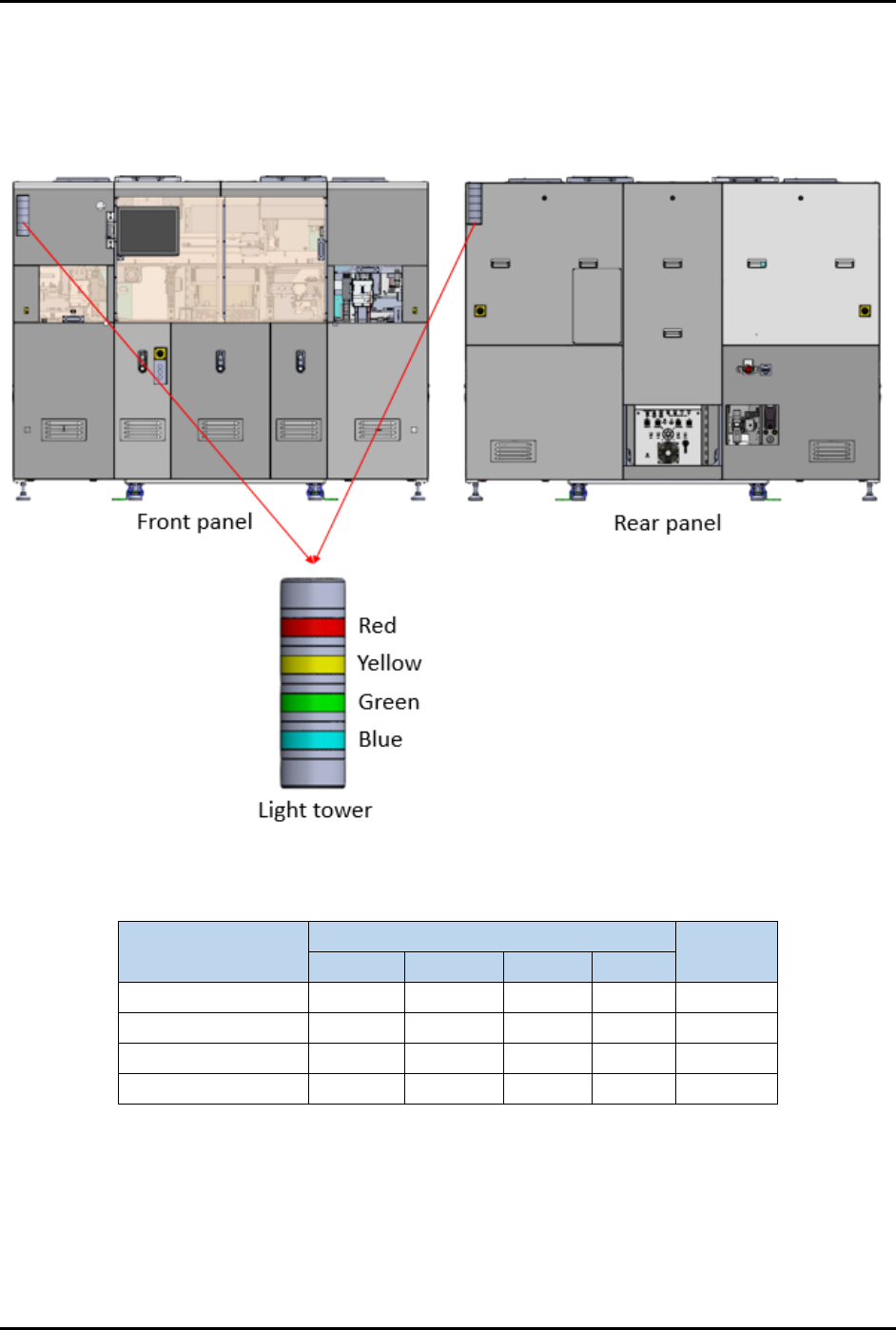
2.16 Light Tower Status Lights
The FlexTRAK-OH Material Handler includes two PLC-controlled light towers that constantly show the
status of the current machine status (Figure 2-12). Light tower color indications are described in
Table 2-2.
Figure 2-12 Light Tower
Table 2-2 Light Tower Status Lights
Machine Status
LED Color
Buzzer
Sound
Red
Yellow
Green
Blue
Running
Solid
Off
Auto mode
Solid
Off
Manual mode
Solid
Off
Alarm
Solid
On
FlexTRAK-OH Material Handling System IOM Manual Safety
© 2023 Nordson Corporation 2-15
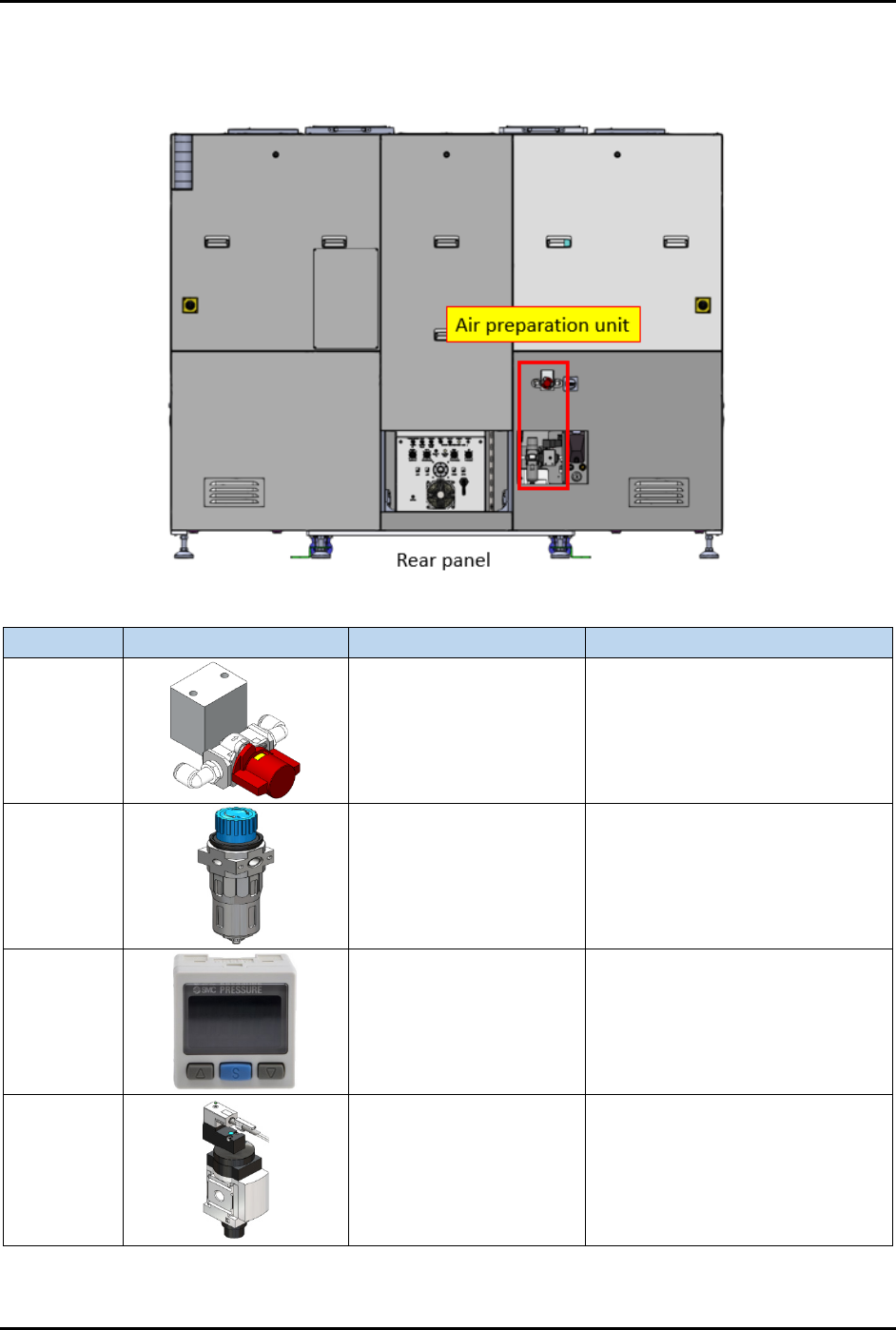
2.17 Air Preparation Unit
The Air Preparation Unit is shown in Figure 2-13.
Item
Part Illustration
Function
Description/Operation Mode
Manual
shut-off
valve
Isolates pneumatic
energy to machine local
components and
integrated equipment
Incoming air state:
SUP: air is supplied
EXH: air is isolated
OFF (0): power is disconnected
Air
pressure
regulator
Increase/decrease air
pressure
Increase when turning knob in "+"
direction.
Decrease when turning knob in
"-" direction.
Air
pressure
gauge
Indicates incoming
compressed air pressure
with configurable upper
and lower limits of air
pressure.
Press related button to configure
the settings. Refer OEM manual:
IMM_xSE30_TFI48GB-A.pdf for
further information.
Soft start
switch
Gradually increases air
pressure when
energized.
Gradually raise the compressed
air pressure to the machine and
automatically shut-off/exhaust the
compressed air.
Controlled by the machine system
(PLC I/O signal).
Figure 2-13 Air Preparation Unit
FlexTRAK-OH Material Handling System IOM Manual Safety
2-16 © 2023 Nordson Corporation
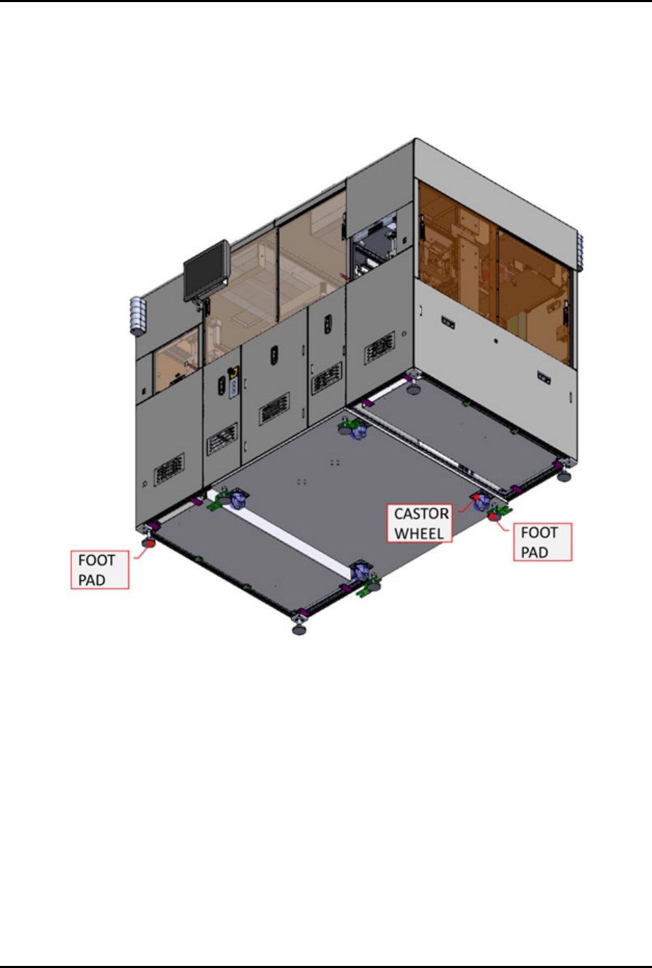
2.18 Foot Pad and Castor Wheel
The foot pad and castor wheels ensures the height of all eight (8) foot pads are aligned with the machine
bottom surface structure (Figure 2-14). Do not install or use the machine in an area that has earthquake
seismic risks. See 2.8 Earthquake Precautions for further details. Do not use the four (4) castor wheels to
move the entire machine during relocation.
Figure 2-14 Foot Pad and Castor Wheel From Machine Bottom