FlexTRAK OH Material Handler Manual.pdf - 第66页
FlexTRAK-OH Material Handli ng System IOM Manual Installation 3-16 © 2023 Nordson C orporation 3.7.2 Magazin e Scale Pla te Adjustm ent The magazine clamp er holder p late (A) provides a maga zine gripper (B) center posi…
FlexTRAK-OH Material Handling System IOM Manual Installation
© 2023 Nordson Corporation 3-15
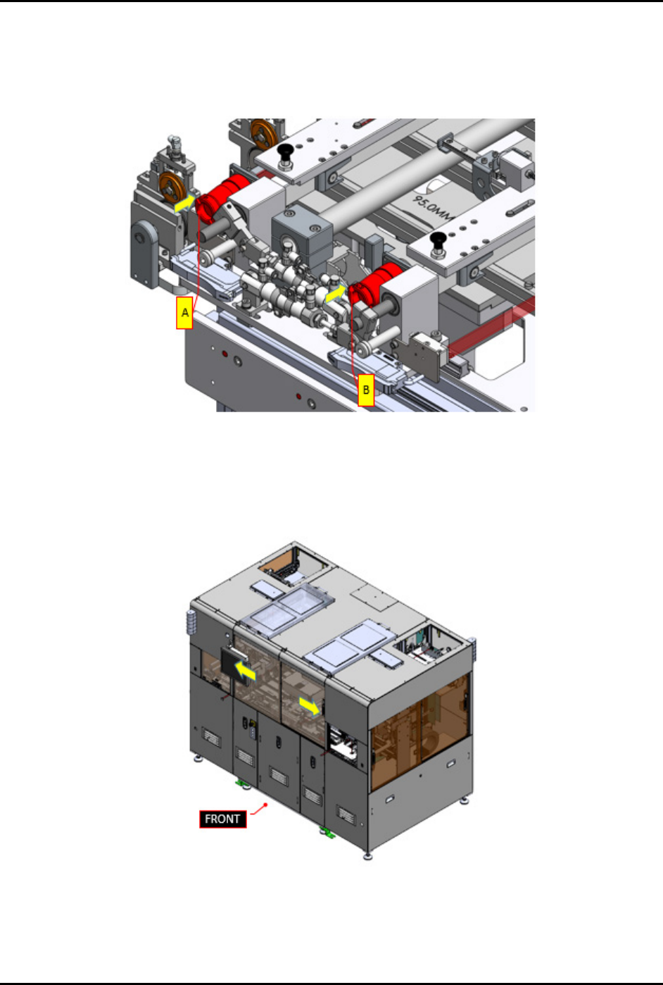
9. Safely plug in claw 1 circular connector (A) and claw 2 circular connector (B) into the
machine (Figure 3-27).
10. Ensure there is no damage at all claw 1 and claw 2 sensor cables, vacuum tube fittings, and
vacuum air manifold feeding.
Figure 3-27 Plug In Circular Connectors
11. Close the front sliding door (Figure 3-28).
12. Press RESET on the pilot switch (Figure 2-9) to acknowledge and clear the current alarm
indicating the front sliding door is open.
Figure 3-28 Close Front Sliding Doors
FlexTRAK-OH Material Handling System IOM Manual Installation
3-16 © 2023 Nordson Corporation
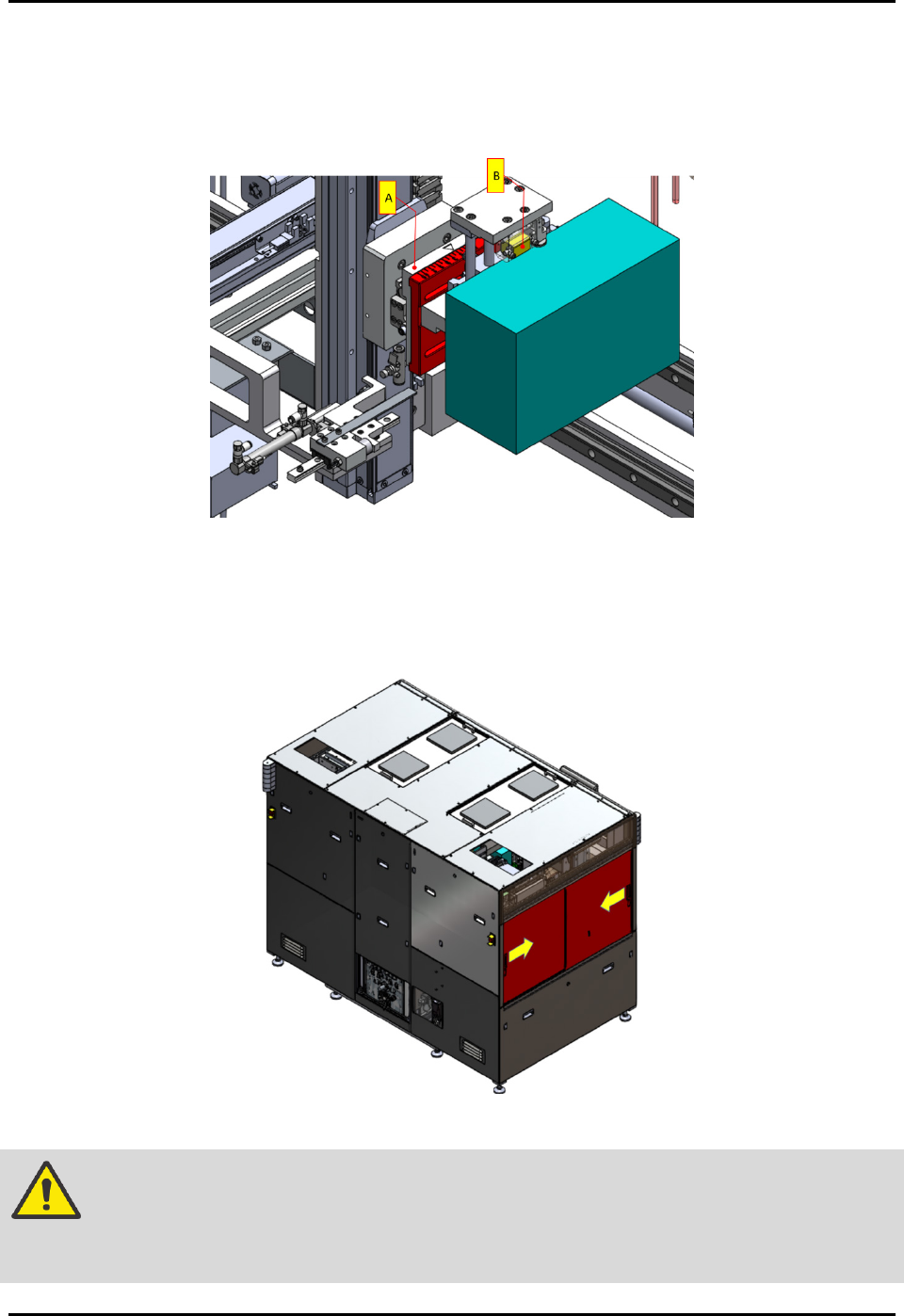
3.7.2 Magazine Scale Plate Adjustment
The magazine clamper holder plate (A) provides a magazine gripper (B) center position against the
clamped magazine and is located in strip loading buffer area and strip unloading buffer area
(Figure 3-29).
Figure 3-29 Magazine Scale Plate Adjustment
To adjust the magazine clamper holder plate:
1. Open the left and right sliding doors to access into the machine interior components from
side view (Figure 3-30).
Figure 3-30 Open Side Sliding Doors
WARNING! Ensure machine is in idle mode by observing the light tower status lights (solid
yellow). Ensure all workpieces (magazine and strip) are removed from the
machine.
FlexTRAK-OH Material Handling System IOM Manual Installation
© 2023 Nordson Corporation 3-17
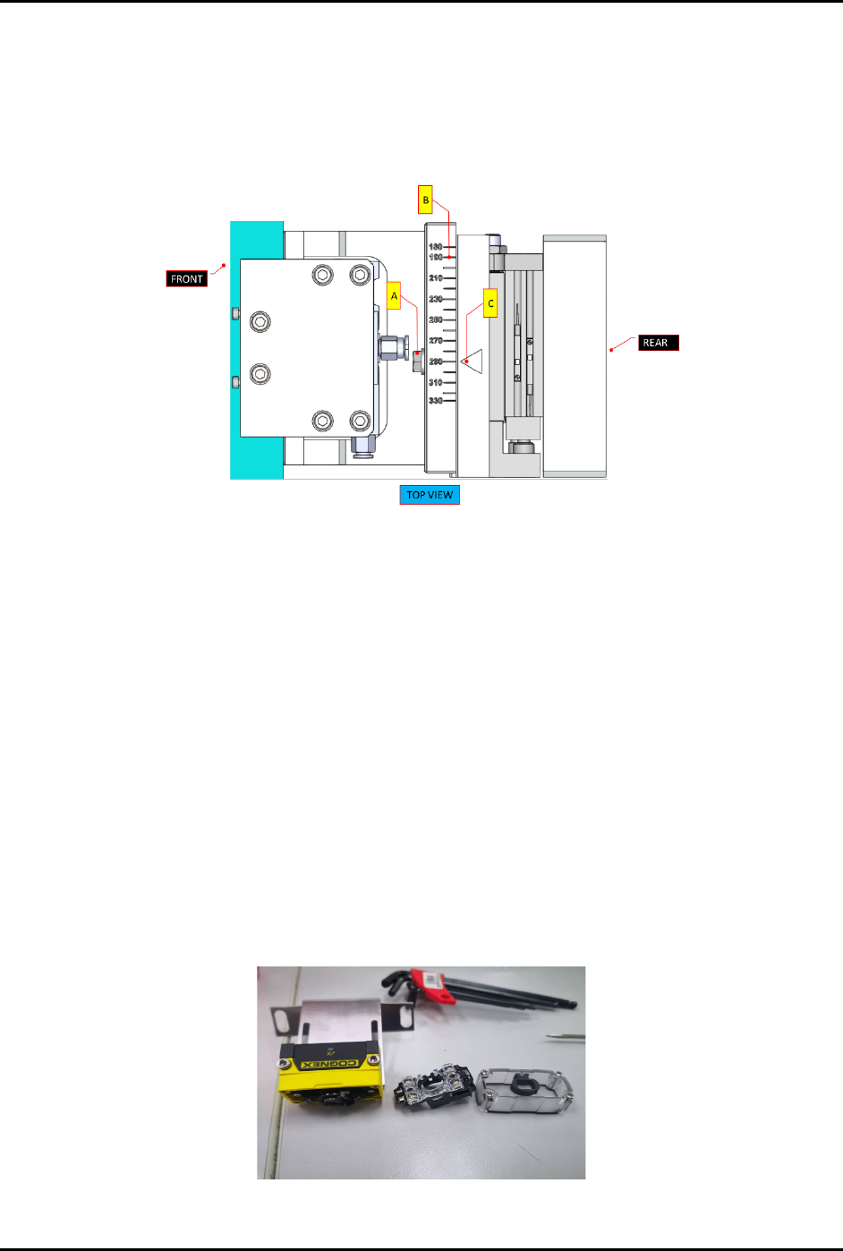
2. Identify position of holder plate (Figure 3-29).
3. Loosen the scale plate tightening bolt (A) with hexagon wrench size ISO = 10
(Figure 3-31).
4. Move the scale ruler (B) so that magazine centering flag (C) will point to the value of
magazine’s length.
Figure 3-31 Magazine Scale Plate Adjustment
5. Tighten the scale plate tightening bolt (A) and torque to 57 lb.-in.
6. Perform Steps 1 through Step 5 above for both the loading and unloading stations.
3.7.3 Magazine Scanner Installation and/or Adjustment (Optional Feature)
Tools and Materials Needed:
• Type C USB
• DataMan software V5.7.0 CR11
To install and or adjust the magazine scanner:
1. For a new scanner, following the steps below to adjust the focus lens before performing
software configuration:
a. Loosen all screws.
b. Remove the cover and flashlight (Figure 3-32).
Figure 3-32 Remove Cover and Flashlight from Magazine Scanner