FlexTRAK OH Material Handler Manual.pdf - 第93页
FlexTRAK-OH Material Handli ng System IOM Manual Material Handler Operation © 2023 Nordson C orporation 4-5 4.6.2 HMI Data Output Indi cator s The HMI output indica tor buttons displ ay a specific machine p rocess or com…
FlexTRAK-OH Material Handling System IOM Manual Material Handler Operation
4-4 © 2023 Nordson Corporation
4.6 HMI Data Input/Output Indicators
4.6.1 HMI Data Input Indicators
The HMI input buttons input data to the machine logic controller. Each label on the button describes its
function. Some buttons use a pictogram/symbol rather than text to describe their functions. See Table 4-1
through Table 4-3 for detailed descriptions of the HMI Data Input buttons.
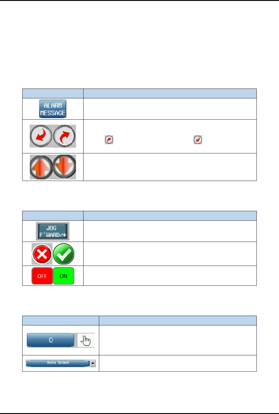
4.6.1.1 Screen Navigation Buttons
Table 4-1 Screen Navigation Buttons
Button Description
Shows the machine HMI screen as labeled on the button text.
Some screens have multiple pages in order to show all
available features and indicators.
Select to move to the next screen or to move to
previous screen.
Scrolls the page up/down.
4.6.1.2 Control Switches
Table 4-2 Control Switches
Button Description
Triggers the function labeled on the button text.
Enables (unlocks) or disables (locks) the motor actuation
switch to jog the axis.
Enables (ON) or disables (OFF) a specific component function.
4.6.1.3 Data Selection and Update Forms
Table 4-3 Data Selection and Update Forms
HMI Object Description
When pressed, the HMI keypad displays so you can
insert a specific decimal value (Example: 1, 20, 300, 000)
for the form function. The data value type is labeled
beside the form.
Click the down arrow to list all available parameters
related to the current screen.
FlexTRAK-OH Material Handling System IOM Manual Material Handler Operation
© 2023 Nordson Corporation 4-5
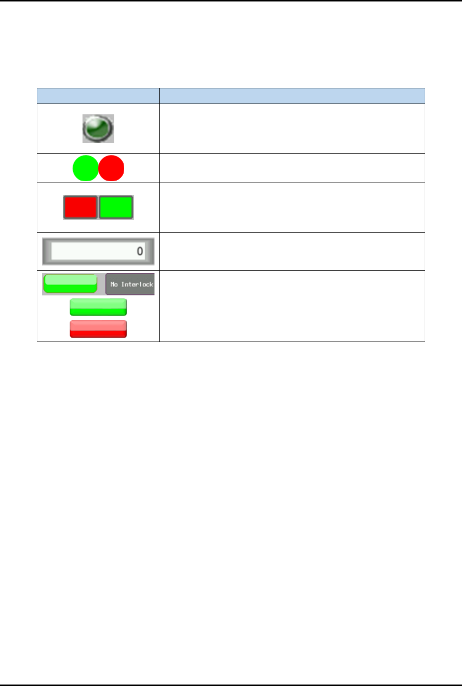
4.6.2 HMI Data Output Indicators
The HMI output indicator buttons display a specific machine process or component availability state. See
Table 4-4 for a detailed description of the HMI Output Indicator buttons.
Table 4-4 HMI Data Output Indicator
HMI Object
Description
Indicates specific motor actuation status as labeled beside
the indicator to show whether an axis control switch is
enabled (light green button) or disabled (dark green
button) to actuate a motor.
Enables (green button) or disables (red button) a specific
station I/O component function.
Enables (green button) or disables (red button) a specific
station process sequence status. Once the station process
sequence is complete, the indicator will be red (process
error) or green (good process).
Shows the current measured value/previously saved
parameter value. The data value type is labeled beside the
box.
Locks (red button) or unlocks (green button) the cylinder’s
switching interlock state.
FlexTRAK-OH Material Handling System IOM Manual Material Handler Operation
4-6 © 2023 Nordson Corporation
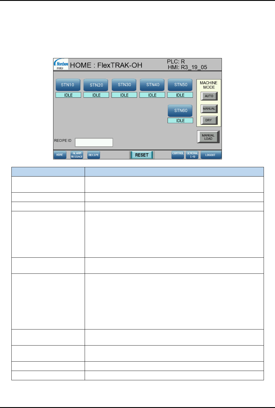
4.7 Home Screen
The Home screen (Figure 4-4) is displayed at system startup.
NOTE Refer to 4.6 HMI Data Input/Output Indicators for detailed information on screen
indicators.
Item
Description
STN10, 20, 30, 40, 50, 60
Shows the machine module control parameters and indicators at
stations 10, 20, 30, 40, 50, and 60.
Idle Indicates current process state.
Recipe ID Indicates current recipe.
Machine Mode
• Auto – Activates the auto mode for machine mechanism
process sequences control.
• Manual – Activates the manual mode for station component
configuration and individual triggering.
• Dry – Activates the mode for machine process sequences to
run without a workpiece present check.
Manual Load
Activates magazine manual loading and unloading ports in the
auto production mode.
Alarm Message
Opens the Alarm Message screen.
• Reset – Deletes the list of alarm messages on the Alarm
Message screen.
• Buzzer On/Off – Turns on/off the alarm sound from buzzer.
• Alarm History Button – Opens the Alarm History screen.
• Clear History – Deletes the list of alarm messages on the
Alarm History screen.
Recipe
Opens the Recipe screen. Refer to 4.8 Call Recipe Screen for
details.
Reset
Press Reset to allow the system to execute process sequences
after the alarm correction.
Control
Refer to 4.9 Control Screen for details.
General I/O
Refer to 4.10 General I/O Screen for details.
Figure 4-4 Home Screen