FlexTRAK OH Material Handler Manual.pdf - 第75页
FlexTRAK-OH Material Handli ng System IOM Manual Installation © 2023 Nordson C orporation 3-25 3.7.5.4 LR - ZH500 S eries Figure 3- 44 LR - ZH500 Series S trip Sensor Table 3-7 Steps to F ine - tune LR - ZH500 S ensor St…
FlexTRAK-OH Material Handling System IOM Manual Installation
3-24 © 2023 Nordson Corporation
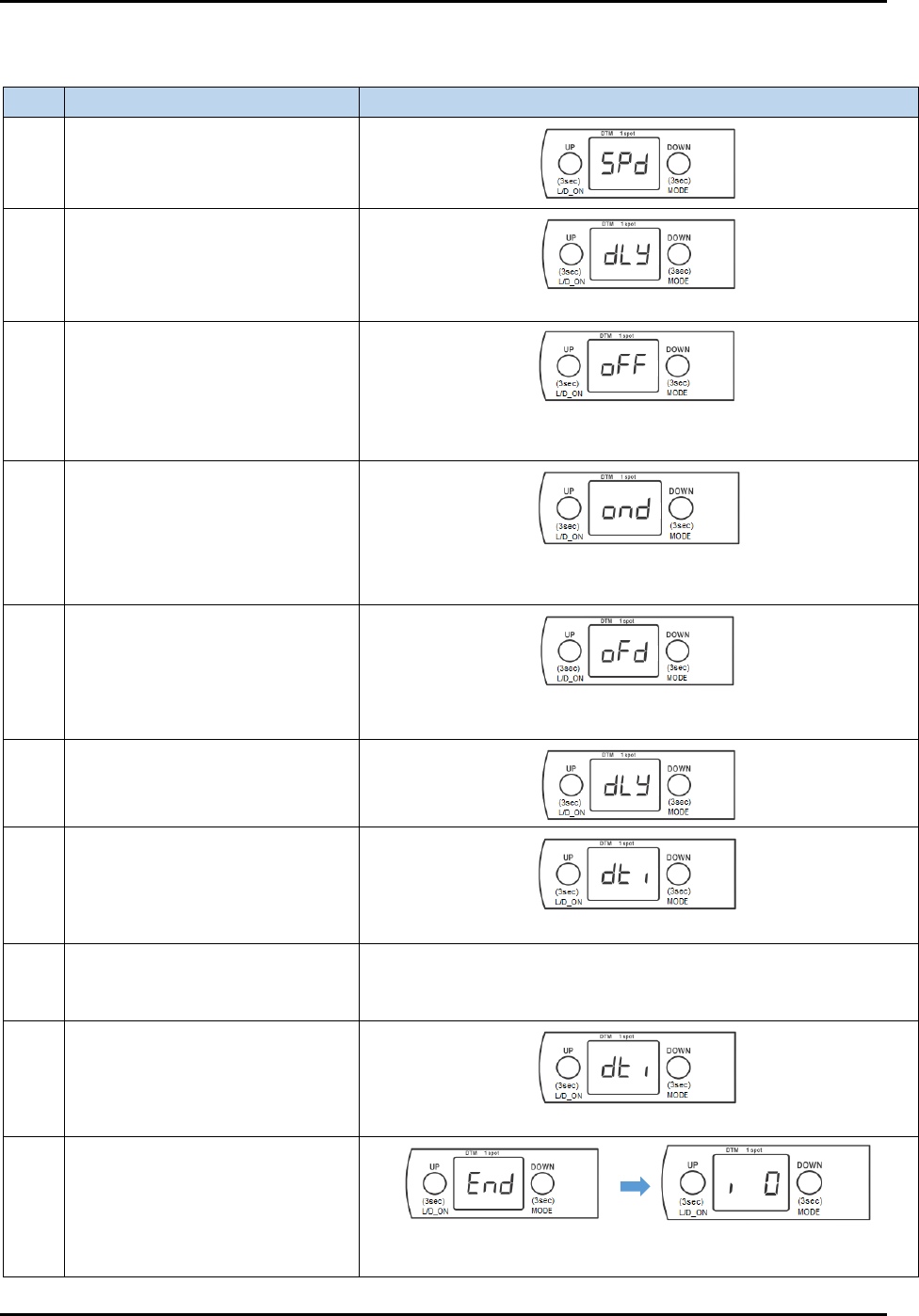
3.7.5.3 Delay Timer Settings
Table 3-6 Set Delay Timer on Strip Sensor
Step Action Display on screen
1
Long press MODE button for 3
to 5 seconds.
2 Press once on DOWN button.
(delay)
3 Press once on UP button.
(default setting – off)
*** blinking ***
4 Press once on UP button.
(on delay)
*** blinking ***
5 Press once on UP button.
(off delay)
*** blinking ***
6 Press once on DOWN button.
7 Press once on DOWN button.
(amount of time for timer)
8 Press once on UP button.
Displays timer (in milliseconds, e.g.: 10, 20, …100, 200), and
blinking. Selects desired value.
Press UP/DOWN consecutively to increase/decrease the value.
9 Press once on DOWN button.
*** blinking ***
10
Long press DOWN button for 3
to 5 seconds to save value.
Returns to original value
before step 1.
FlexTRAK-OH Material Handling System IOM Manual Installation
© 2023 Nordson Corporation 3-25
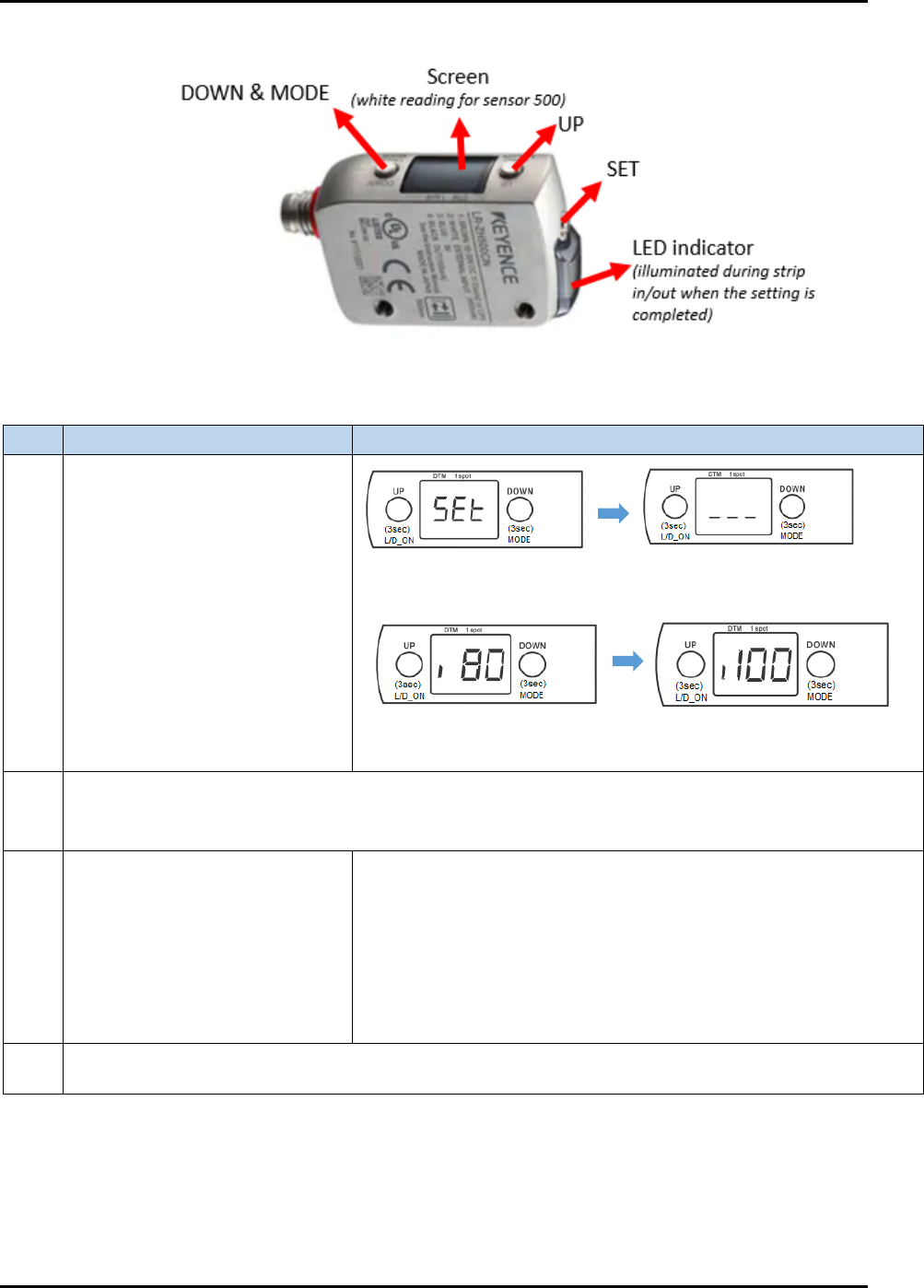
3.7.5.4 LR-ZH500 Series
Figure 3-44 LR-ZH500 Series Strip Sensor
Table 3-7 Steps to Fine-tune LR-ZH500 Sensor
Step
Action
Display on screen
1
Simultaneously press once on
both UP and SET buttons.
Note: Ensure no strip is present
or common background while
doing this step.
Next, displays any value, and blinking. Example:
2
When all settings are done, "DTM" and "1 spot" indicators will light up in step 1.
DTM (orange light) stands for datum/universal change detection (UCD)
1 spot (green light) stands for sensor stability
3
Press UP or DOWN button to
adjust value.
If set value > display value in Step 1, press UP
If set value < display value in Step 1, press DOWN
After adjusting the value, new value will blink and immediately
change on screen. It will be autosaved after a while.
The LED indicator at the side will illuminate, which means the
signal is successfully detected in the machine.
See 3.7.5.2 How to Set Threshold Limit in Strip Sensor for further
details.
4
Add off delay in sensor. The purpose of this setting is to prevent a false alarm signal from a reflective
die telling the system that the strip is absent. See 3.7.5.3 Delay Timer Settings for further details.
***blinking***
80 = Current threshold limit
100 = actual optimum reading
(without strip)
FlexTRAK-OH Material Handling System IOM Manual Installation
3-26 © 2023 Nordson Corporation
3.7.6 Fine-tuning the Slot Mapping Sensor
The slot mapping sensor and amplifier is assembled in the input elevator module (Station 20).
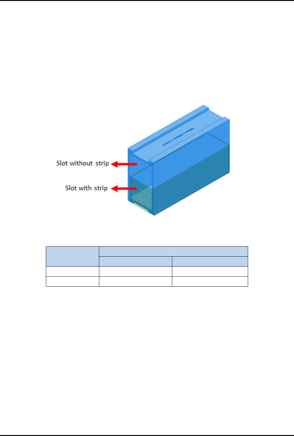
3.7.6.1 Production Test Flow and Running Concept
1. Half of the magazine is filled with strips and the other half is empty (Figure 3-45).
2. The strip barcode scanner will scan to see if there is a strip in the magazine slot. If the
magazine slot is empty, the gripper will skip the magazine lifting index during the strip
kicking process.
Example:
Figure 3-45 Magazine Slot With and Without Strip
Table 3-8 Example of Slot Mapping Test
Magazine Slot
Target Threshold Value in Amplifier
Readable
Unreadable
(a) With strip
20
0
(b) Without strip
0
20
• In the magazine slot with a strip (a), the threshold value shown in the amplifier increases
(higher value) when the strip is readable (strip present) and decreases (zero or lower value)
when the strip is unreadable (strip absent).
• In the magazine slot without a strip (b), the threshold value shown in the amplifier increases
(higher value) when strip is unreadable (strip absent) and decreases (zero or lower value)
when strip is readable (strip present).