FlexTRAK OH Material Handler Manual.pdf - 第52页
FlexTRAK-OH Material Handli ng System IOM Manual Installation 3-2 © 2023 Nordson C orporation 3.4 Uncrating and Placi ng the FlexTRAK- OH 1. Safely d ismantle the mach ine crat e as inst ructed by the crate d ismantlin g…

© 2023 Nordson Corporation 3-1
3 Installation
3.1 Overview
This chapter describes installation procedures for the FlexTRAK-OH Material Handler. This chapter
covers the following topics:
• Transporting the
• Uncrating and Placing the
• Installing the Cables and Tubing
• Initial Setup Procedure/Pre-Teaching
• Setup Procedures
3.2 Safety First
Operation of your FlexTRAK-OH Material Handler involves mechanical devices, air pressure, and
electrical power. It is essential that every person servicing or operating the FlexTRAK-OH fully
understands all hazards, risks, and safety precautions. When properly operated and maintained, the
FlexTRAK-OH Material Handler should be safe and reliable. Refer to Section 2 - Safety prior to
installation and operation
.
3.3 Transporting the FlexTRAK-OH
1. Ensure the crate is in good condition by inspecting the impact indicator (tiltwatch and
shockwatch) that are attached to the side of the crate (Figure 3-1).
2. Inform the machine manufacturer if the shockwatch has been activated.
Figure 3-1 Crate Impact Indicator (Tiltwatch and Shockwatch)
3. Use a forklift with a 2000 kg capacity. Safely lift the crate and place it at the designated
place.
FlexTRAK-OH Material Handling System IOM Manual Installation
3-2 © 2023 Nordson Corporation
3.4 Uncrating and Placing the FlexTRAK-OH
1. Safely dismantle the machine crate as instructed by the crate dismantling instructions.
2. Remove any screws that anchored the machine with the crate floors.
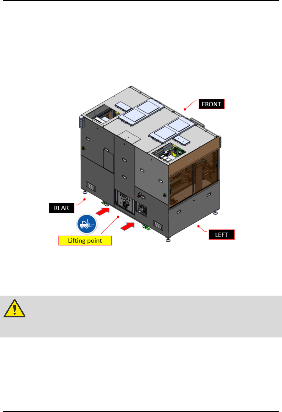
3. Identify the machine lifting point.
4. Place in the forklift fork under the machine profile as guarded by the lifting point label on
the machine (Figure 3-2).
Figure 3-2 Machine Lifting Point
5. Jack up the machine until the leveling foot pad gap with the floor is more than 10 cm.
6. Safely move the machine to the designated production place.
WARNING! Do not use the four castor wheels installed on machine bottom to move the entire
machine during relocation (Figure 2-14). This may cause machine damage when
the area is uneven or has an earthquake seismic risk.
7. Setup the machine orientation and clearance distance requirement as required by the
production plant. See 8.5 Clearance Distance Requirement.
8. Safely move down the forklift and place the machine in a safe area.
9. Remove all tie wraps from the machine components.
Cut the tie wrap carefully without damaging the machine cables, wires, tubing, etc.
FlexTRAK-OH Material Handling System IOM Manual Installation
© 2023 Nordson Corporation 3-3
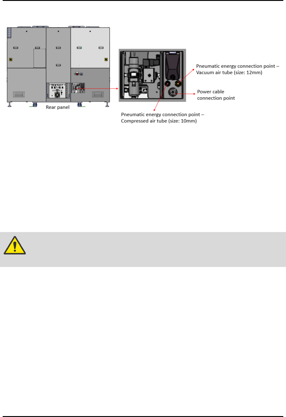
3.5 Installing the Cables and Tubing
Figure 3-3 Power Cable and Pneumatic Energy Connection Points
3.5.1 Connecting the Electrical Power
To connect the electrical power:
1. Identify the electrical power cable supplied with the machine.
The electrical power cable is routed through the cable gland point.
The electrical power cable is installed with the machine electrical terminal block.
NOTE The socket for the electric receptable or power outlet connection is not supplied
with the machine.
WARNING! Only a certified electrician should perform the electrical wiring and socket
installation procedure.
2. Lockout the energy at the isolator switch and the plant electrical distribution panel (if
applicable). See 2.19.1 Electrical Power Lockout for details.
3. Prepare the factory electrical power outlet socket. Specifications for the supplied power
cable are as below:
• Cable wire list: Live (x1), Neutral (x1), Ground (x1)
• Cable length: 10 meters
• Cable size: 8 AWG, 10 mm
• Rated voltage: 220/240 V
• Ambient temperature: 60 °C
4. Safely plan the power cable route to the electrical power outlet.
5. Connect all cables to the appropriate electrical power socket.
6. Connect the machine electrical feeding cable socket to the power outlet (Figure 3-3).