FlexTRAK OH Material Handler Manual.pdf - 第60页
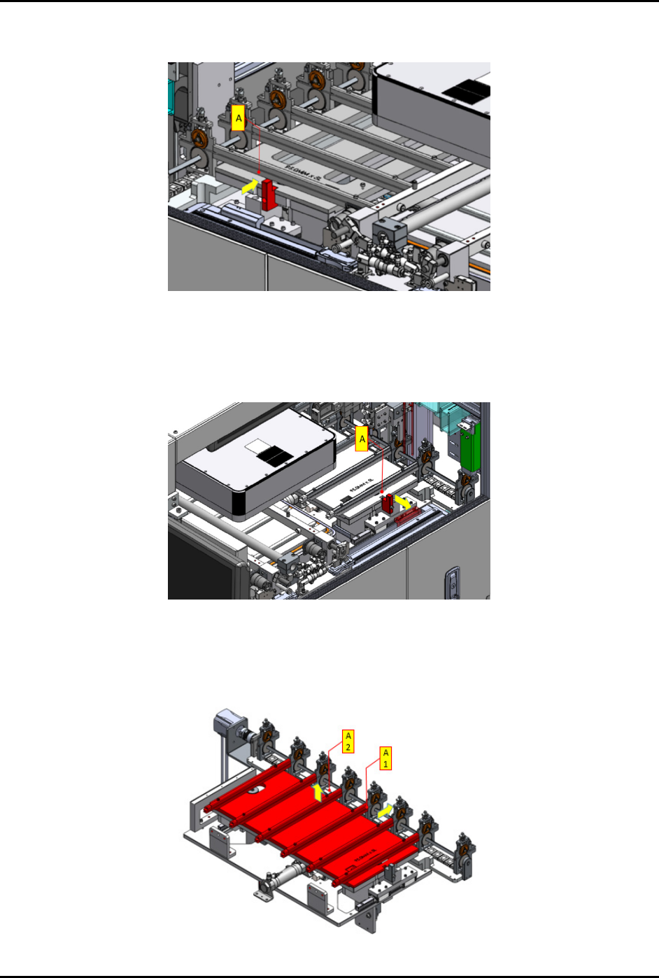
FlexTRAK-OH Material Handli ng System IOM Manual Installation 3-10 © 2023 Nordson C orporation g. Push (A) in the dire ction indica ted by the yel low arrow to loc k the conve rsion kit ( Figure 3- 16 ). Figure 3- 16 Loc…
FlexTRAK-OH Material Handling System IOM Manual Installation
© 2023 Nordson Corporation 3-9
4. Follow the steps below to remove and assemble the strip loading lane:
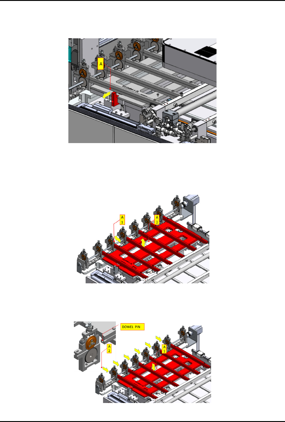
a. Pull (A) in the direction indicated by the yellow arrow to unlock the conversion kit
(Figure 3-13).
Figure 3-13 Unlock Kit in Loading Lane
b. Pull out the pinch wheel assembly (A1) (Figure 3-14).
c. Manually lift the kit up (A2) and remove from the machine.
d. Safely place the kit on a conversion keeping rack.
Figure 3-14 Remove Loading Lane from Machine
e. Install the correct conversion kit for new production recipe (A1) (Figure 3-15).
f. Align the pinch wheel assemblies with the dowel pins on each loading lane (A2).
Figure 3-15 Install the Conversion Kit
FlexTRAK-OH Material Handling System IOM Manual Installation
3-10 © 2023 Nordson Corporation
g. Push (A) in the direction indicated by the yellow arrow to lock the conversion kit
(Figure 3-16).
Figure 3-16 Lock Conversion Kit in Place
5. Follow the steps below to remove and assemble strip unloading lane:
a. Pull (A) in the direction indicated by the yellow arrow to unlock the conversion kit
(Figure 3-17).
Figure 3-17 Unlock Conversion Kit in Place
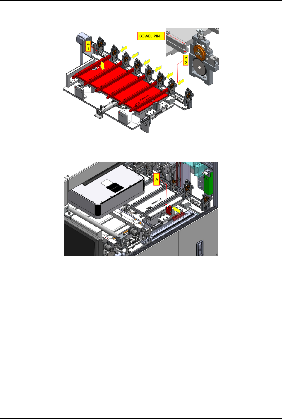
b. Pull out the conversion kit from the pinch wheel assembly (A1) and manually lift the kit
up (A2) and remove from the machine (Figure 3-18).
c. Safely place the kit on a conversion keeping rack.
Figure 3-18 Remove Conversion Kit from Machine
FlexTRAK-OH Material Handling System IOM Manual Installation
© 2023 Nordson Corporation 3-11
d. Place the correct conversion kit for new production recipe (A1). Install the pinch wheel
assembly with the dowel pins on unloading lane (A2) (Figure 3-19).
Figure 3-19 Place Correct Unloading Lane to Machine
e. Push (A) in the direction indicated by the yellow arrow to lock the conversion kit.
Figure 3-20 Lock Conversion Kit in Place
6. Follow the steps below to remove and assemble the chamber conversion kit at the plasma
chamber station:
a. Push out the strip transfer claw – base assembly from the chamber area (A1)
(Figure 3-21).
b. Manually lift the kit up (A2) and remove from the machine. Safely place the kit on a
conversion keeping rack.