FlexTRAK OH Material Handler Manual.pdf - 第46页
FlexTRAK-OH Material Handli ng System IOM Manual Safety 2-16 © 2023 Nordson C orporation 2.18 Foot Pad and Castor Wheel The foot pad and castor wheels ensur es the height of all eight ( 8) foot pads a re aligned wit h th…
FlexTRAK-OH Material Handling System IOM Manual Safety
© 2023 Nordson Corporation 2-15
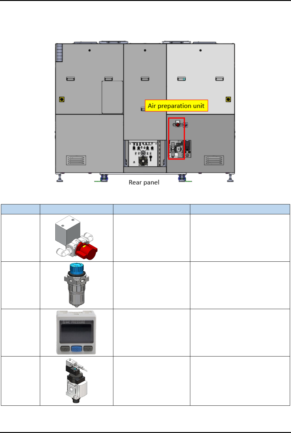
2.17 Air Preparation Unit
The Air Preparation Unit is shown in Figure 2-13.
Item
Part Illustration
Function
Description/Operation Mode
Manual
shut-off
valve
Isolates pneumatic
energy to machine local
components and
integrated equipment
Incoming air state:
SUP: air is supplied
EXH: air is isolated
OFF (0): power is disconnected
Air
pressure
regulator
Increase/decrease air
pressure
Increase when turning knob in "+"
direction.
Decrease when turning knob in
"-" direction.
Air
pressure
gauge
Indicates incoming
compressed air pressure
with configurable upper
and lower limits of air
pressure.
Press related button to configure
the settings. Refer OEM manual:
IMM_xSE30_TFI48GB-A.pdf for
further information.
Soft start
switch
Gradually increases air
pressure when
energized.
Gradually raise the compressed
air pressure to the machine and
automatically shut-off/exhaust the
compressed air.
Controlled by the machine system
(PLC I/O signal).
Figure 2-13 Air Preparation Unit
FlexTRAK-OH Material Handling System IOM Manual Safety
2-16 © 2023 Nordson Corporation
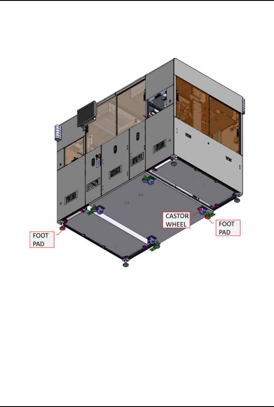
2.18 Foot Pad and Castor Wheel
The foot pad and castor wheels ensures the height of all eight (8) foot pads are aligned with the machine
bottom surface structure (Figure 2-14). Do not install or use the machine in an area that has earthquake
seismic risks. See 2.8 Earthquake Precautions for further details. Do not use the four (4) castor wheels to
move the entire machine during relocation.
Figure 2-14 Foot Pad and Castor Wheel From Machine Bottom
FlexTRAK-OH Material Handling System IOM Manual Safety
© 2023 Nordson Corporation 2-17
2.19 Service Shutdown
WARNING! Inform and obtain permission from the authorized personnel before de-energizing
the machine electrical power.
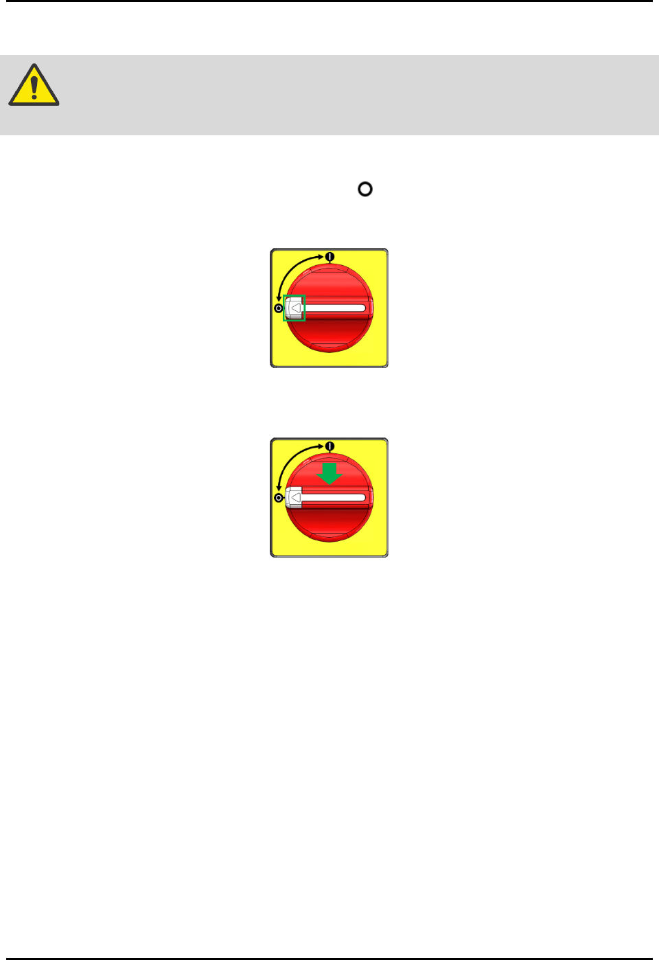
2.19.1 Electrical Power Lockout/Tagout
1. Twist the isolator switch to the off position (Figure 2-15).
2. Locate the lockout point position, then press the white button (Figure 2-15).
Figure 2-15 Isolator Switch
3. Apply the LOTO kit at the lockout point (Figure 2-16).
Figure 2-16 Apply LOTO Kit On Isolator Switch
4. Verify electrical de-energize status by using an electrical voltage measuring tool for AC
source. Measure for Live (L) and Neutral (N). Result obtained should be read as 0 V ~AC.
NOTE
Wait for 10 minutes before attempting to perform maintenance, servicing, or
troubleshooting of electrical modules (e.g., servo motors).
Electrical energy is always present at:
• Power cable to the terminal block (XT10, XT11)
• Terminal block (XT10, XT11) to the isolator switch