FlexTRAK OH Material Handler Manual.pdf - 第175页
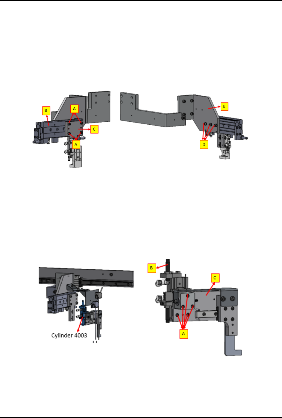
FlexTRAK-OH Material Handli ng System IOM Manual Maintenance © 2023 Nordson C orporation 5-11 5.9.6 Unloader E levator Kick er X - Axis (C YL 4002) To remove and replace cylind er 4002 ( Figure 5-8 ): 1. Loosen four (4) …
FlexTRAK-OH Material Handling System IOM Manual Maintenance
5-10 © 2023 Nordson Corporation
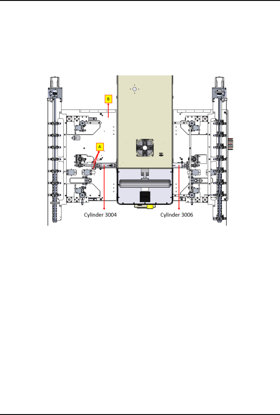
5.9.5 Input/Output Transfer X-Axis (CYL 3004 and 3006)
To remove and replace cylinders 3004 and 3006 (Figure 5-7):
1. Loosen two (2) screws (A) to separate the cylinder with the buffer base guider (B).
2. Remove the cylinder from each station.
3. Reverse the steps above to install a new cylinder into the module.
Figure 5-7 Input/Output Transfer X-Axis Cylinders (Double Acting Cylinders)
FlexTRAK-OH Material Handling System IOM Manual Maintenance
© 2023 Nordson Corporation 5-11
5.9.6 Unloader Elevator Kicker X-Axis (CYL 4002)
To remove and replace cylinder 4002 (Figure 5-8):
1. Loosen four (4) screws (A) to separate the cylinder (B) with the right mounting plate (C).
2. Loosen three (3) screws (D) to separate the cylinder with the left mounting plate (E).
3. Remove the cylinder from the module.
4. Reverse the steps above to install a new cylinder into the module.
Figure 5-8 Unloader Elevator Kicker X-Axis Cylinder
5.9.7 Unloader Elevator Kicker Z-Axis (CYL 4003)
To remove and replace cylinder 4003 (Figure 5-9):
1. Loosen five (5) screws (A) to separate the cylinder (B) with the kicker pusher module.
2. Remove the cylinder from unloader magazine elevator module.
3. Reverse all the steps above to replace a new cylinder into the module.
Figure 5-9 Unloader Elevator Kicker Z-Axis Cylinder
FlexTRAK-OH Material Handling System IOM Manual Maintenance
5-12 © 2023 Nordson Corporation
5.10 Belt Tensioning Adjustment
Tools and Materials Needed:
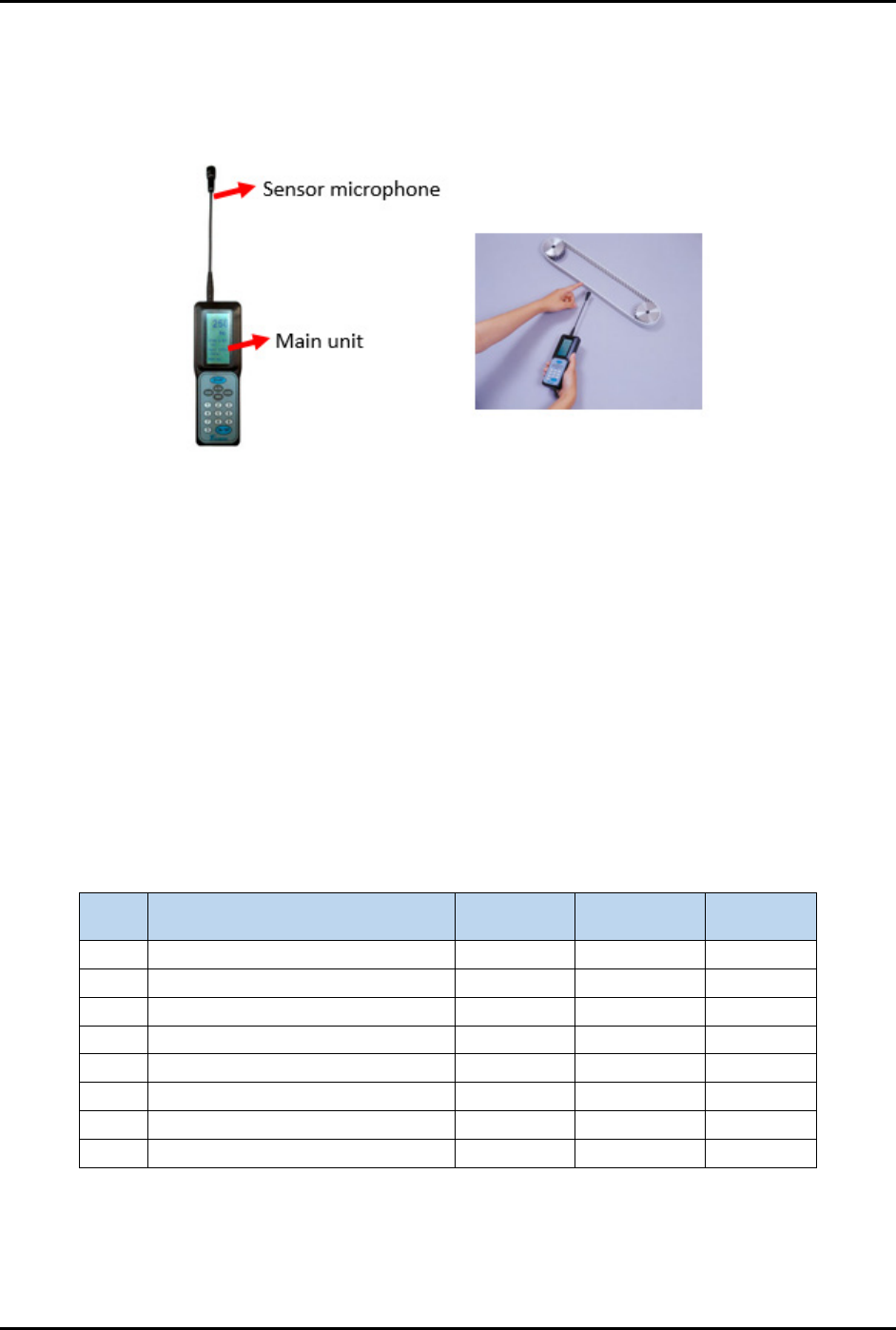
• Belt Tension Meter (Figure 5-10)
Figure 5-10 Belt Tension Meter
The FlexTRAK-OH measures the belt tension using sound waves detected from the sensor microphone.
Measurement unit can be switched between newton (N) and frequency (Hz). Before adjusting, observe the
factory recommended specifications requirement (MASS, SPAN, and tension values).
To adjust the belt tension:
1. Install sensor microphone on the main unit.
2. Follow specification, enter MASS value and SPAN value into the main unit (Table 5-2).
3. Move the sensor microphone close to the belt, flip the belt with finger and start taking
measurement.
4. To get a pass result, tested tension value must be within the range of recommended tension
value as shown in following table.
Table 5-2 Belt Tension Values
No. Belt Module
SPAN Value
(mm)
Mass Value
(kg/m)
Tension
Value (N)
1 Loader kicker 60 0.025 12 – 17
2 Unloader stopper 60 0.025 12 – 17
3 Loader elevator Z-axis 80 0.025 32 – 42
4 Unloader elevator Z-axis 80 0.025 32 – 42
5 Loader lifter 100 0.025 32 – 42
6 Unloader lifter 100 0.025 32 – 42
7 Loader elevator Y-axis 60 0.025 92 – 102
8 Unloader elevator Y-axis 60 0.025 92 – 102