FlexTRAK OH Material Handler Manual.pdf - 第14页
FlexTRAK-OH Material Handli ng System IOM Manual Introductio n 1-4 © 2023 Nordson C orporation 1.4.2 Rear View F eatures Rear view featu res are shown in Figu re 1-2 . The callout numbers in the illustration corre spond …

FlexTRAK-OH Material Handling System IOM Manual Introduction
© 2023 Nordson Corporation 1-3
Table 1-1 Front View Component Description
Item Name Description
1
HEPA Filter and LED Lighting
(hidden)
The HEPA Filter and LED Lighting filters dust particles
for clean air circulation inside the machine. LED lighting
is integrated to support setup and maintenance
activities.
2
RFID Tag Writer and Reader
(hidden)
Each conversion kit component is registered and
verified through the RFID Tag Writer and Reader. This
device ensures that the configuration between
conversion kit and associated production recipe is
correct.
3 FlexTRAK HMI Screen
The FlexTRAK HMI Screen is the main controller for the
FlexTRAK-OH System. All information associated with
production is displayed here.
4 Light Tower
The Light Tower indicates machine status and fault alert
through the color indication and audible alarm.
5 Magazine Loading Input
The Magazine Loading Input is a magazine input port so
the operator can manually place the magazine into the
platform.
6
Control Pendant Storage
Compartment
The machine control pendant is stored in the Control
Pendant Storage Compartment and can be plugged into
any of the pendant interface ports throughout the
machine.
7
Pilot Buttons and Front Emergency
Machine Off (EMO)
The Pilot Buttons consist of START, RESET, and STOP
buttons that provide machine controls.
Pressing the STOP button does not require machine
initialization and the machine operator can continue the
current production process once the triggered alarm is
rectified or acknowledged.
The EMO button cuts machine power at the motor driver
through the safety relay devices. The control connection
is driven by a hardwired configuration. Press the EMO
button during an emergency situation only.
8 Magazine Unloading Output
The Magazine Unloading Output is a magazine output
port so the operator can manually remove the magazine
from the platform.
9
Direct Current (DC) Electrical
Power Panel
Electrical DC circuit components are assembled inside
the Direct Current (DC) Electrical Power Panel.
10 Side Sliding Door
The Side Sliding Door provides guarded access to the
machine's side interior components.
11 Front Sliding Door
The Front Sliding Door provides guarded access to the
machine's front interior components.
12
Overhead Magazine Unloading
Output
The Overhead Magazine Unloading Output is an output
port where an output magazine to be pickup by the
overhead conveyor system is located.
13 Overhead Magazine Loading Input
The Overhead Magazine Loading Input receives a
magazine from the overhead conveyor system and
transfers the magazine to the magazine station.
FlexTRAK-OH Material Handling System IOM Manual Introduction
1-4 © 2023 Nordson Corporation
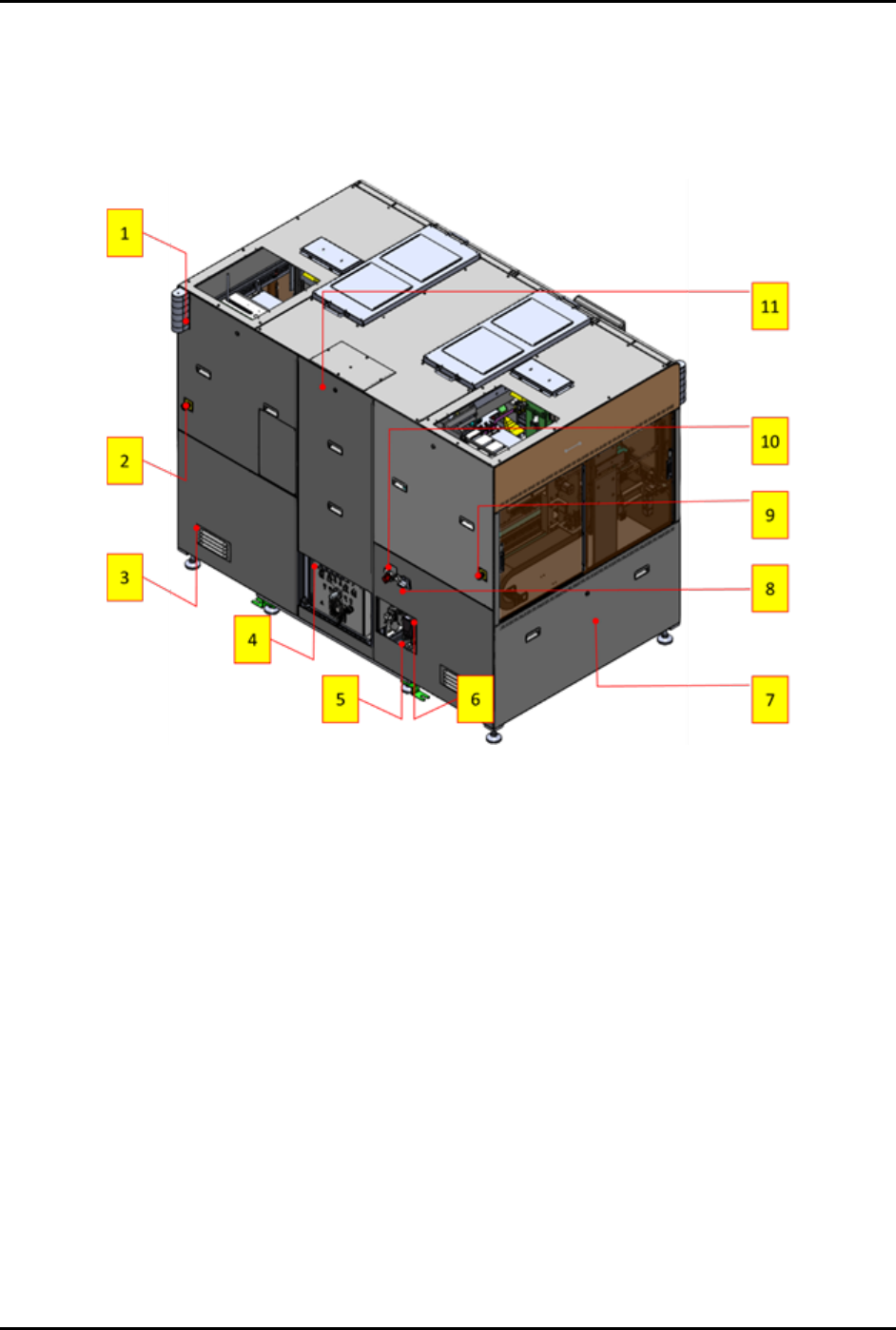
1.4.2 Rear View Features
Rear view features are shown in Figure 1-2. The callout numbers in the illustration correspond to the item
numbers in Table 1-2.
Figure 1-2 Rear View Features

FlexTRAK-OH Material Handling System IOM Manual Introduction
© 2023 Nordson Corporation 1-5
Table 1-2 Rear View Component Description
Item Name Description
1 Rear Tower Light
The Rear Tower Light indicates machine status and fault
alert through the color indication and audible alarm.
2 EMO (Right)
The Right EMO button cuts machine power at the motor
driver through the safety relay devices. The control
connection is driven by a hardwired configuration. Press the
EMO button during an emergency situation only.
3 Electrical Panel Air Flow Vent
The Electrical Panel Air Flow Vent provides cool air
circulation around the electrical panel compartments.
4
Plasma Process Gas Tube
Fitting
Refer to the FlexTRAK Series Plasma Systems Installation,
Operation, and Maintenance Manual for specific information
regarding the FlexTRAK-S System.
5 Compressed Air Tube Fitting
The Compressed Air Tube Fitting is the main air feeding port
and is connected to the facilities compressed air supply
valve.
6 Ethernet Communication Port
The Ethernet Communication Port provides communication
with the machine Programmable Logic Controller (PLC) for
the system software update.
7
Alternate Current (AC)
Electrical Power Panel
Electrical AC circuit components are assembled inside the
Alternate Current (AC) Electrical Power Panel.
8
Electrical Isolator/Main
Disconnect Switch
The Electrical Isolator/Main Disconnect Switch is the
Lockout/Tagout (LOTO)
point for electrical energy isolation.
9 EMO (Left)
The Left EMO button cuts machine power at the motor
driver through the safety relay devices. The control
connection is driven by a hardwired configuration. Press the
EMO button during an emergency situation only.
10
Compressed Air Main Shut-Off
Valve
The Compressed Air Main Shut-Off Valve is the LOTO point
for the pneumatic energy isolation.
11 Machine Rear Access Panel
The Machine Rear Access Panel provides guarded access
to the machine's rear interior components.