FlexTRAK OH Material Handler Manual.pdf - 第119页
FlexTRAK-OH Material Handli ng System IOM Manual Material Handler Operation © 2023 Nordson C orporation 4-31 4.12.2.5 M otor Con trol in Axis 1 (Y-A xis ) Pressing the MOT OR button on th e Device Contro l screen ( Figur…
FlexTRAK-OH Material Handling System IOM Manual Material Handler Operation
4-30 © 2023 Nordson Corporation
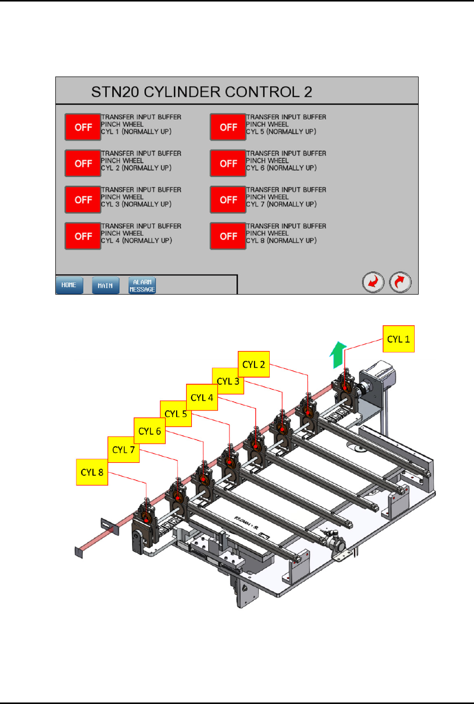
4.12.2.4 Cylinder Control 2
OFF – selected component function is not active and has not reached the target position
ON – selected component function is active and has reached the target position
Figure 4-41 Station 20 – Cylinder Control 2 Screen
Figure 4-42 Station 20 – Cylinder Control 2 Locations
FlexTRAK-OH Material Handling System IOM Manual Material Handler Operation
© 2023 Nordson Corporation 4-31
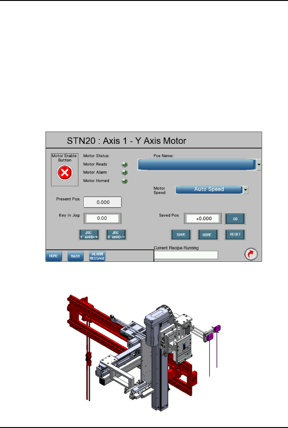
4.12.2.5 Motor Control in Axis 1 (Y-Axis)
Pressing the MOTOR button on the Device Control screen (Figure 4-37) displays a configuration list of
motor driver parameters and the axis platform position.
Refer to 4.11 Station Main Menu Layout for interface descriptions.
The following selections are available in the "Pos Name" drop down list:
• Standby
• To Stn10 grippers (top conv)
• Place position (first lane)
• Manual load port position (bottom conv)
• 1
st
strip scan (SO only)
• Place position (last lane)
Figure 4-43 Station 20 – Axis 1 (Y-Axis Motor) Screen
The red highlighted area in Figure 4-44 shows the location of Axis 1 (Y-axis) in Station 20.
Figure 4-44 Station 20 – Axis 1 (Y-Axis Motor) Locations
FlexTRAK-OH Material Handling System IOM Manual Material Handler Operation
4-32 © 2023 Nordson Corporation
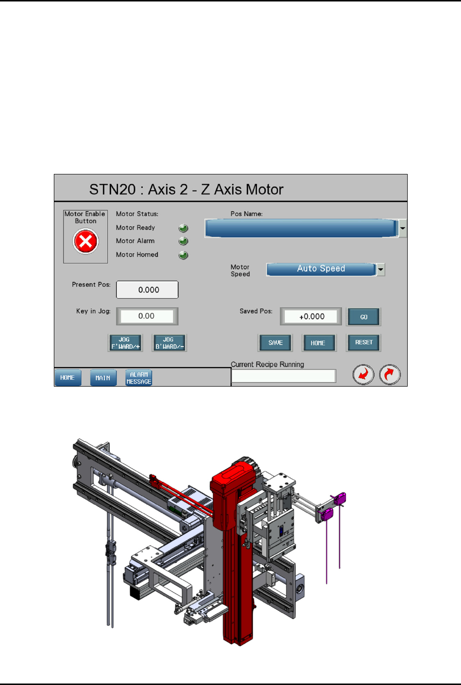
4.12.2.6 Motor Control in Axis 2 (Z-Axis)
Refer to 4.11 Station Main Menu Layout for interface descriptions.
The following selections are available in the "Pos Name" drop down list:
• Standby
• To Stn10 grippers (top conv)
• Place position (first strip bottom)
• Manual load port position (bottom conv)
• 1
st
strip scan (SO only)
• Place position (last strip top)
Figure 4-45 Station 20 – Axis 2 (Z-Axis Motor) Screen
The red highlighted area in Figure 4-46 shows the location of Axis 1 (Z-axis) in Station 20.
Figure 4-46 Station 20 – Axis 2 (Z-Axis Motor) Locations