FlexTRAK OH Material Handler Manual.pdf - 第50页
在线预览 FlexTRAK OH Material Handler Manual.pdf PDF 文档。
FlexTRAK-OH Material Handling System IOM Manual Safety
© 2023 Nordson Corporation 2-19
2.19.2 Pneumatic Energy Lockout/Tagout
Turn the shut-off valve knob handle from SUP to the EXH position (Figure 2-13). Energy will be
isolated.
WARNING! The pneumatic lines coming into the shut-off knob remain energized after the
knob switch has been turned to Off position. Shut-off valve knob isolates
pneumatic energy to machine local components and integrated equipment.
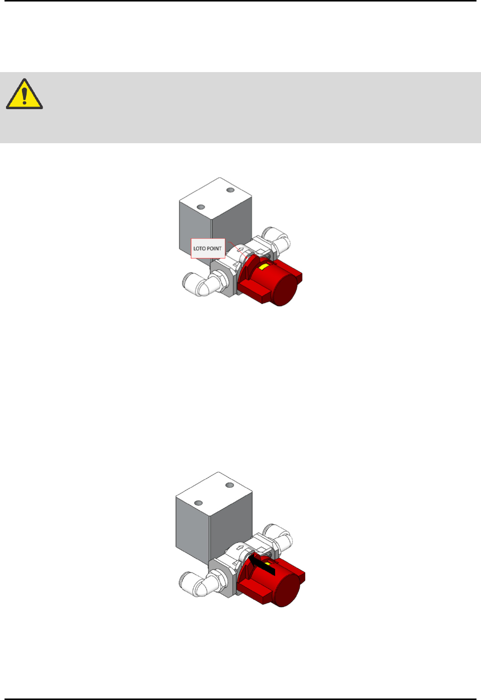
1. Locate the lockout point position (Figure 2-18).
Figure 2-18 LOTO Kit Anchoring Point for Shut-Off Valve
2. Verify compressed air de-energize status by listening to the exhausted air sound or by
verifying the reading in air pressure gauge (Figure 2-13).
The reading should be zero bar.
The compressed air pressure reading will be unavailable when electrical power is
de-energized as the gauge is a digital pressure meter type.
3. Turn off the gas supply safety valve
4. Apply the LOTO kit on the shut-off valve knob (Figure 2-19).
Figure 2-19 Apply LOTO Kit On Shut-Off Valve Knob

© 2023 Nordson Corporation 3-1
3 Installation
3.1 Overview
This chapter describes installation procedures for the FlexTRAK-OH Material Handler. This chapter
covers the following topics:
• Transporting the
• Uncrating and Placing the
• Installing the Cables and Tubing
• Initial Setup Procedure/Pre-Teaching
• Setup Procedures
3.2 Safety First
Operation of your FlexTRAK-OH Material Handler involves mechanical devices, air pressure, and
electrical power. It is essential that every person servicing or operating the FlexTRAK-OH fully
understands all hazards, risks, and safety precautions. When properly operated and maintained, the
FlexTRAK-OH Material Handler should be safe and reliable. Refer to Section 2 - Safety prior to
installation and operation
.
3.3 Transporting the FlexTRAK-OH
1. Ensure the crate is in good condition by inspecting the impact indicator (tiltwatch and
shockwatch) that are attached to the side of the crate (Figure 3-1).
2. Inform the machine manufacturer if the shockwatch has been activated.
Figure 3-1 Crate Impact Indicator (Tiltwatch and Shockwatch)
3. Use a forklift with a 2000 kg capacity. Safely lift the crate and place it at the designated
place.