FlexTRAK OH Material Handler Manual.pdf - 第169页
FlexTRAK-OH Material Handli ng System IOM Manual Maintenance © 2023 Nordson C orporation 5-5 5.8 Lubrication Requir ements Lubrication s hould be perf ormed aft er cleaning and i nspecting movi ng mechanism s. The FlexTR…
FlexTRAK-OH Material Handling System IOM Manual Maintenance
5-4 © 2023 Nordson Corporation
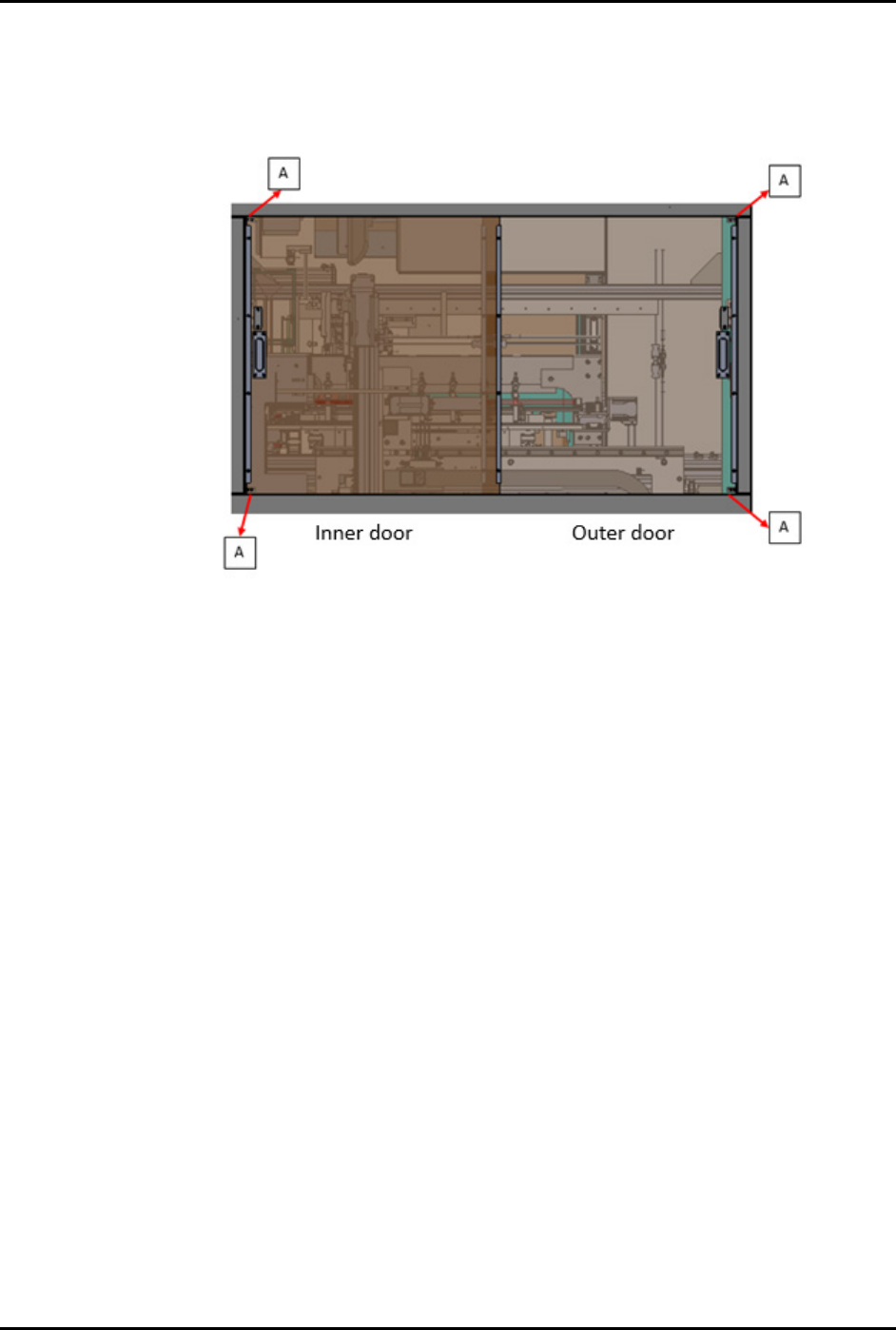
5.7 Removal and Replacement of Access Panels
NOTE The following removal and replacement steps are applicable to the access doors on
machine front, left, and right sides. Remove outer door first, then followed by inner door.
To remove outer door:
1. Remove the two retaining screws from top left and bottom left sides to separate the Delrin
block (A) from the sliding door.
2. Slowly lift up the door and pull it away from machine.
To remove inner door:
1. Remove the two retaining screws from top right and bottom right sides to separate the
Delrin block (A) from the sliding door.
2. Slowly lift up the door and pull it away from machine.
To replace the access doors:
1. Reverse the steps above.
FlexTRAK-OH Material Handling System IOM Manual Maintenance
© 2023 Nordson Corporation 5-5
5.8 Lubrication Requirements
Lubrication should be performed after cleaning and inspecting moving mechanisms. The FlexTRAK-OH
Material Handler components requiring lubrication and the procedures to perform the lubrication are
included below.
Tools and Materials Needed:
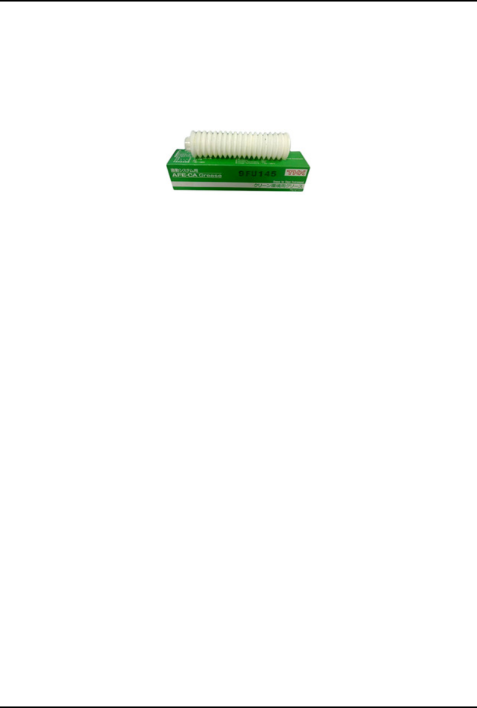
• Lubricating grease (AFE-CA Grease-THK) (Figure 5-1).
Figure 5-1 AFE-CA Grease- THK
• Soft, lint-free shop rag
• Personal Protective Equipment as applicable
5.8.1 Lubricating Process
To perform the lubrication process:
1. Using the AFE-CA Grease and a soft cloth, clean the
ball screw and sliding guide.
2. If necessary, wipe off excess grease and spills.
FlexTRAK-OH Material Handling System IOM Manual Maintenance
5-6 © 2023 Nordson Corporation
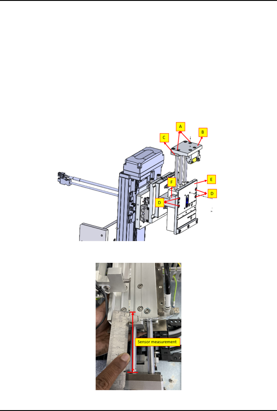
5.9 Common Cylinder Replacement
5.9.1 Loader and Unloader Elevator Gripper (CYL 2001 and 4001)
To remove and replace the loader and unloader elevator gripper cylinder (Figure 5-2):
1. Loosen two (2) screws (A) to separate the mounting plate (B) with the cylinder (C).
2. Loosen four (4) screws (D) to separate the magazine side plate (E) with the cylinder holder
plate (F).
3. Safely remove the cylinder from the module.
4. Reverse the steps above to install a new cylinder into the module.
Before installing the new cylinder, ensure the sensor position is properly measured and
marked (Figure 5-3).
Figure 5-2 Loader and Unloader Elevator Gripper (CYL 2001 and 4001)
Figure 5-3 Measure Sensor Position