FlexTRAK OH Material Handler Manual.pdf - 第131页
FlexTRAK-OH Material Handli ng System IOM Manual Material Handler Operation © 2023 Nordson C orporation 4-43 4.12.4.2 Device Control Screen Label Description Cylinder Shows the control list of electro - pneumatic c ylind…
FlexTRAK-OH Material Handling System IOM Manual Material Handler Operation
4-42 © 2023 Nordson Corporation
4.12.4 Station 40
The red highlighted area in Figure 4-63 shows the location of Station 40 (transfer output module) in the
FlexTRAK-OH.
Figure 4-63 Station 40 – Transfer Output Module Location
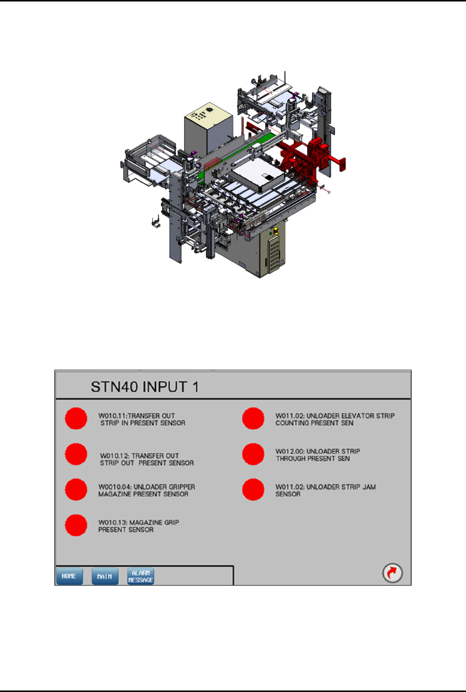
4.12.4.1 Input Screen
Main Screen – Refer to 4.11 Station Main Menu Layout for interface descriptions.
Input Mode – Refer to 4.10 General I/O Screen for interface descriptions.
Figure 4-64 Station 40 – Input 1 Screen
FlexTRAK-OH Material Handling System IOM Manual Material Handler Operation
© 2023 Nordson Corporation 4-43
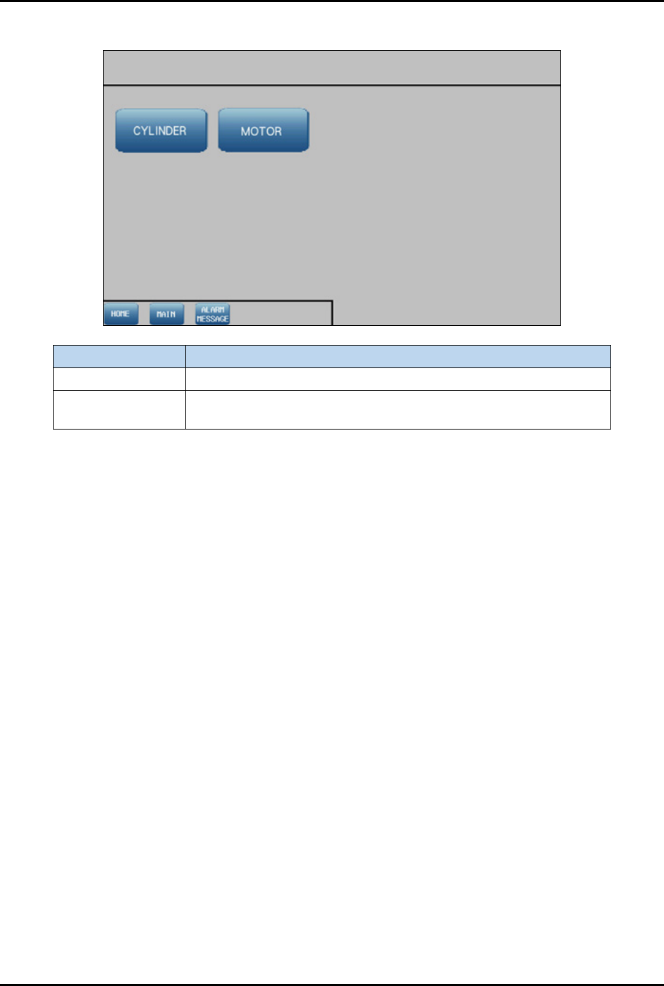
4.12.4.2 Device Control Screen
Label
Description
Cylinder Shows the control list of electro-pneumatic cylinders.
Motor
Shows the configuration list of motor driver parameters and the
axis platform position.
Figure 4-65 Device Control Screen
FlexTRAK-OH Material Handling System IOM Manual Material Handler Operation
4-44 © 2023 Nordson Corporation
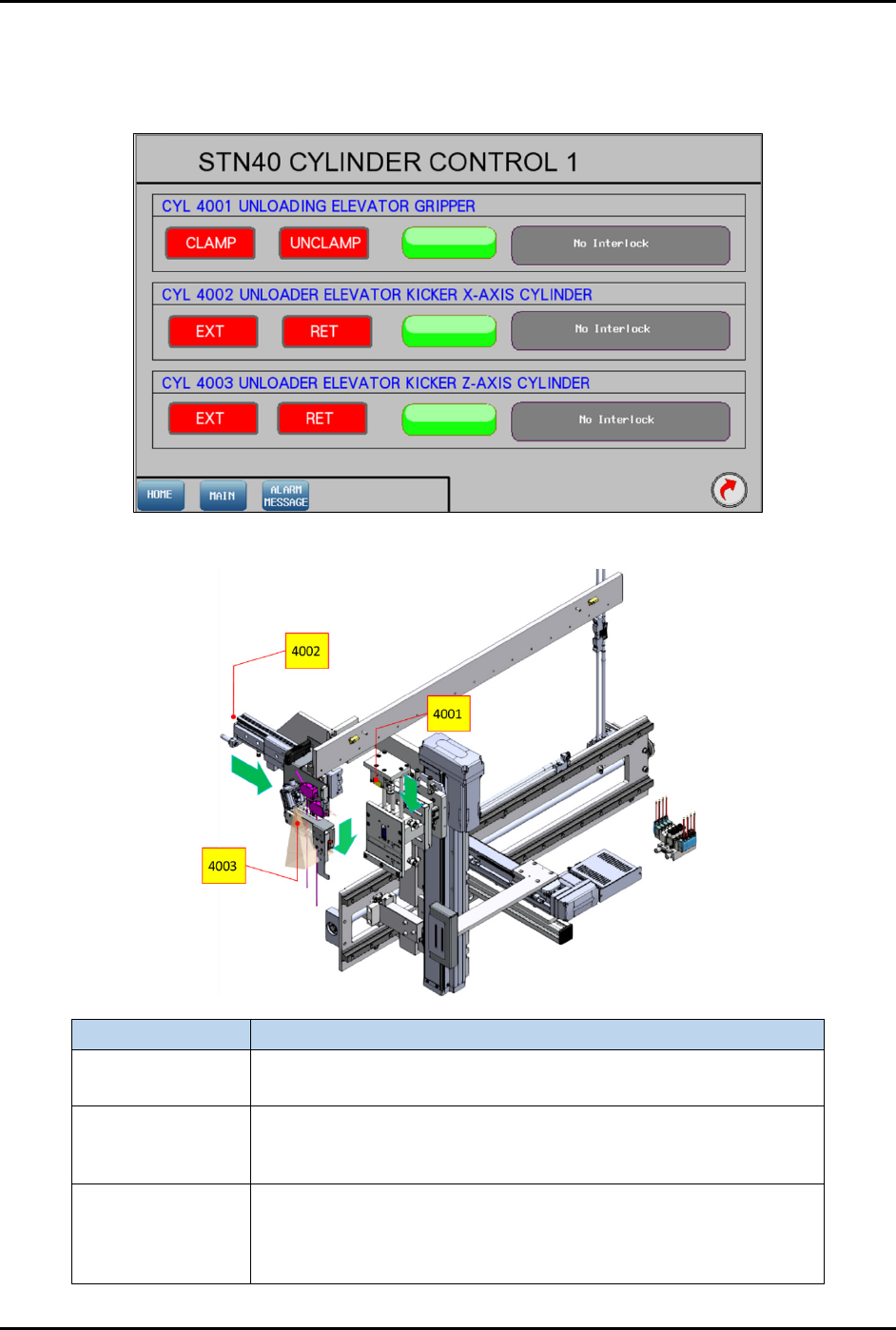
4.12.4.3 Cylinder Control 1
Pressing the CYLINDER button on the Device Control screen (Figure 4-65) will show the control list of
electro-pneumatic cylinders.
Figure 4-66 Station 40 – Cylinder Control 1 Screen
Label
Description
CYL 4001
Clamp – Grip magazine.
Unclamp – Release magazine.
CYL 4002
EXT – Pushes the treated strip into the magazine slot completely
after the pinch wheel has retracted up.
RET – Pulls kicker out from the magazine slot.
CYL 4003
EXT – Moves the kicker down to strip kicking position when strip
has been transferred out by the pinch wheel and W010.11 is
turned off.
RET – Lifts the kicker from the strip kicking position.
Figure 4-67 Station 40 – Cylinder Control 1 Location