FlexTRAK OH Material Handler Manual.pdf - 第21页
FlexTRAK-OH Material Handli ng System IOM Manual Introductio n © 2023 Nordson C orporation 1-11 1.5.5 Strip Transfe r – Claw (Stn30) Item Name Description 1 Loader Claw 2 Limit Sensors D etect s if the claw is disengaged…
FlexTRAK-OH Material Handling System IOM Manual Introduction
1-10 © 2023 Nordson Corporation
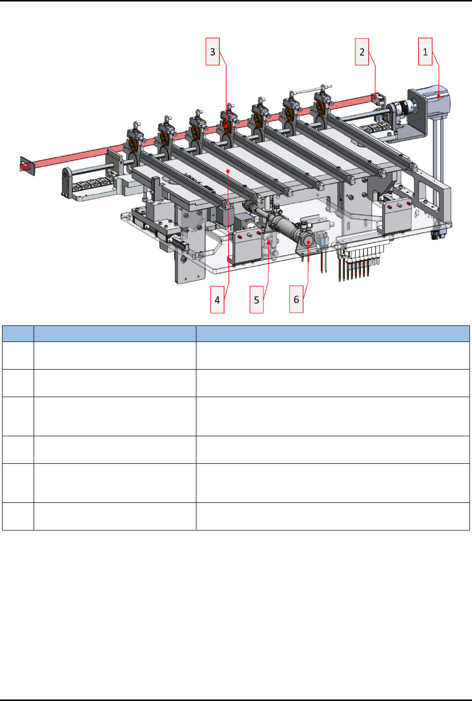
1.5.4 Strip Transfer – Loading (Stn30)
Item Name Description
1
Axis 3 Actuator: Pinch Wheel
Roller In
Transfers an untreated strip to strip clawing position.
2
Loader Strip Through Present
Sensor
Checks that strips are not protruding into the gap between
magazine and input buffer lanes.
3
Transfer Input Buffer Pinch Wheel
Cylinder
Exerts pinching pressure through the pinch wheels onto
the strip. Correct pinch pressure ensures that sufficient
force is applied to the strip to effect transfer.
4 Conversion Kit: Input Buffer Lane
Input strip buffer conversion kit. Conversion kits are
specific to strip size.
5
Cylinder 3003: Input Transfer
Z-Axis
Elevates the input buffers to the same Z-axis position as
the plasma chamber rails to facilitate clawing of strips
into/out of plasma chamber.
6
Cylinder 3004: Input Transfer
X-Axis
Engages the Input Buffer Lanes with the plasma chamber
rails for "Zero Gap" transfer of strips.
Figure 1-7 Strip Transfer – Loading (Stn30)
FlexTRAK-OH Material Handling System IOM Manual Introduction
© 2023 Nordson Corporation 1-11
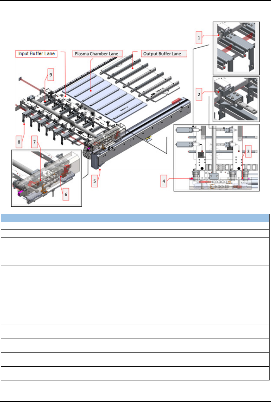
1.5.5 Strip Transfer – Claw (Stn30)
Item
Name
Description
1
Loader Claw 2 Limit Sensors
Detects if the claw is disengaged from magnetic coupling.
2
Unloader Claw 1 Limit Sensors
Detects if the claw is disengaged from magnetic coupling.
3
Unloader Claw 1 Strip Present
Sensor
Detects strip protrusion between the plasma chamber and the
output buffer lane.
4
Loader Claw 2 Strip Present
Sensor
Detects strip protrusion between the plasma chamber and the
input buffer lane.
5 Axis 4: Transfer Actuator
Transfers Loader Claw 2 and Unloader Claw 1 assemblies to
the following positions:
• Standby
• Load position
• Plasma position
• Unload position
• Plasma check position
• Unload check position
6 Cylinder Loader Claw 2
Toggles the claws between clawing (down) and standby (up)
positions.
7 Cylinder Unloader Claw 1
Toggles the claws between clawing (down) and standby (up)
positions.
8 Loader Claws
Transfers untreated strips from input buffer lanes into the
plasma chamber lanes.
9 Unloader Claws
Transfers treated strips from plasma chamber lanes into the
output buffer lanes.
Figure 1-8 Strip Transfer – Claw (Stn30)
FlexTRAK-OH Material Handling System IOM Manual Introduction
1-12 © 2023 Nordson Corporation
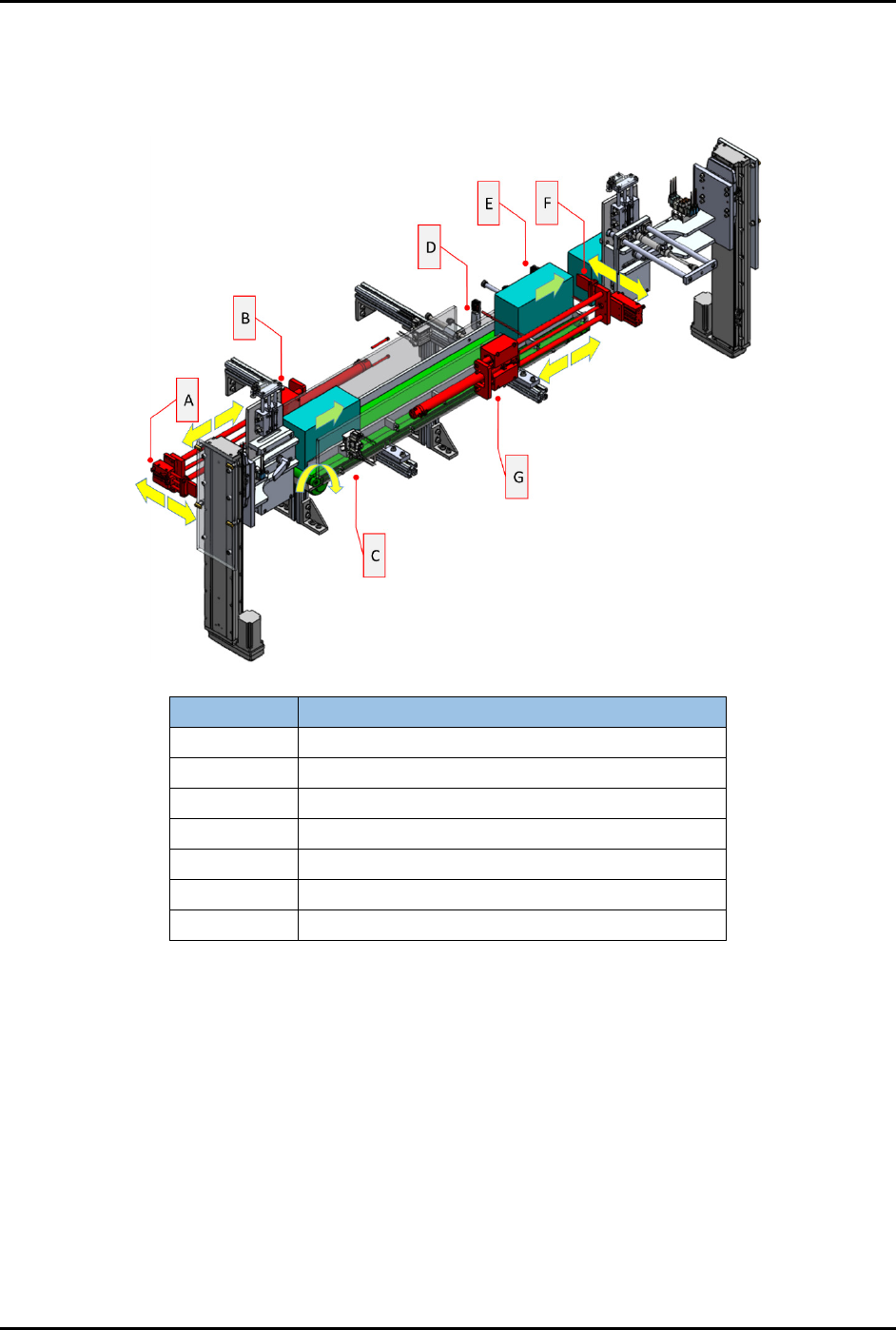
1.5.6 Overhead Return Conveyor (Stn60)
This module provides mechanism components (Items A-G) to transfer the magazine from loader lifter
(Figure 1-5) module to unloader lifter module (Figure 1-12).
Item Name
A Magazine Claw – Push In
B
Magazine Pusher Into Conveyor Cylinder
C
Magazine Conveyor – Induction Motor
D Magazine Present Sensor
E
Magazine Present Sensor
F
Magazine Claw – Push Out
G
Magazine Pusher Out From Conveyor Cylinder
Figure 1-9 Overhead Return Conveyor (Stn60)