FlexTRAK OH Material Handler Manual.pdf - 第54页
FlexTRAK-OH Material Handli ng System IOM Manual Install ation 3-4 © 2023 Nordson C orporation 3.5.2 Compressed Air an d Vacuum Tube 1. Identify the conne ction points for compres sed air and vacuum air ( Figure 3-3). 2.…
FlexTRAK-OH Material Handling System IOM Manual Installation
© 2023 Nordson Corporation 3-3
3.5 Installing the Cables and Tubing
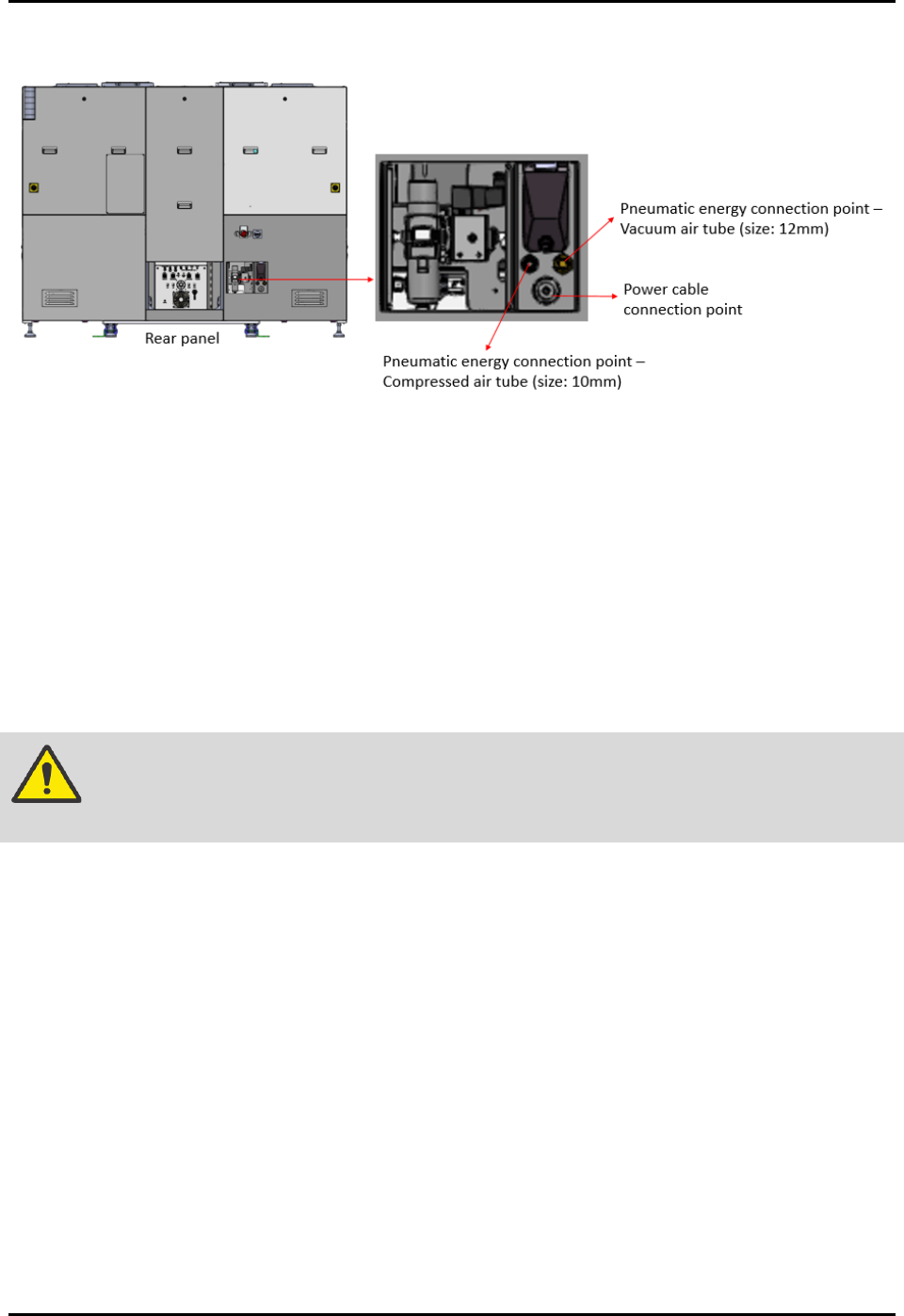
Figure 3-3 Power Cable and Pneumatic Energy Connection Points
3.5.1 Connecting the Electrical Power
To connect the electrical power:
1. Identify the electrical power cable supplied with the machine.
The electrical power cable is routed through the cable gland point.
The electrical power cable is installed with the machine electrical terminal block.
NOTE The socket for the electric receptable or power outlet connection is not supplied
with the machine.
WARNING! Only a certified electrician should perform the electrical wiring and socket
installation procedure.
2. Lockout the energy at the isolator switch and the plant electrical distribution panel (if
applicable). See 2.19.1 Electrical Power Lockout for details.
3. Prepare the factory electrical power outlet socket. Specifications for the supplied power
cable are as below:
• Cable wire list: Live (x1), Neutral (x1), Ground (x1)
• Cable length: 10 meters
• Cable size: 8 AWG, 10 mm
• Rated voltage: 220/240 V
• Ambient temperature: 60 °C
4. Safely plan the power cable route to the electrical power outlet.
5. Connect all cables to the appropriate electrical power socket.
6. Connect the machine electrical feeding cable socket to the power outlet (Figure 3-3).

FlexTRAK-OH Material Handling System IOM Manual Installation
3-4 © 2023 Nordson Corporation
3.5.2 Compressed Air and Vacuum Tube
1. Identify the connection points for compressed air and vacuum air (Figure 3-3).
2. Lockout the pneumatic energy at the shut-off valve and the plant pneumatic air distribution
panel (if applicable). See 2.19.2 Pneumatic Energy Lockout for details.
3. Plug in the applicable air tube to the specific connection point. Air tube fitting sizes are
listed as below:
• Vacuum air: 12 mm
• Compressed air: 10 mm
4. Safely route the tubes to the vacuum air and compressed air outlets. Ensure the tubes are not
tangled while routing the tubes.
5. Connect all tubes to the intended vacuum air and compressed air outlets.
3.6 Initial Setup Procedure/Pre-Teaching
The following initial set up procedure must be performed before running the production strips.
To perform the initial setup procedure:
1. Ensure the facilities energy output is within the range of machine operation specifications
(voltage and current) rating. The machine operating air pressure is 5.5 bar. The compressed
air pressure gauge and HMI input screen will self-power on.
2. Ensure light tower status light is solid yellow. See 2.16 Light Tower Status Lights.
3. Ensure the correct production recipe is selected.
4. Ensure the correct magazine dimensions are selected. See 1.7 Magazine Dimensions.
5. Ensure the following setup is correct:
a. Specification of strip lane conversion kit (Figure 3-4) must be equivalent to the
production recipe lane quantity (e.g., 5L or 6L) and magazine width. See
3.7.1 Conversion Kit Replacement for details.
Figure 3-4 Strip Lane Conversion Kit
b. The configuration value of magazine gripper scaling plate (Figure 3-5) must correspond
with the magazine length. See 3.7.2 Magazine Scale Plate Adjustment for details.
FlexTRAK-OH Material Handling System IOM Manual Installation
© 2023 Nordson Corporation 3-5
Figure 3-5 Magazine Gripper Scaling Plate
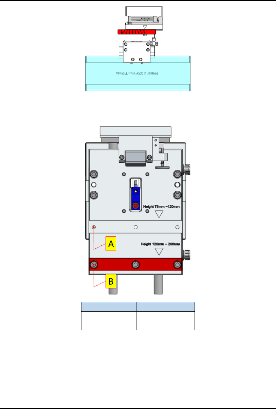
c. The magazine lifter height scaling plate must be configured according to the magazine
height range classification shown in Figure 3-6.
Magazine Height
Use
75 – 120 mm
(A) Top slot
121 – 200 mm
(B) Bottom slot
Figure 3-6 Magazine Lifter Height Scaling Plate
6. Ensure machine is in manual mode. This can be checked from the Home screen of mobile
control pendant (Figure 2-8).
7. Ensure the user access account is logged out.