FlexTRAK OH Material Handler Manual.pdf - 第129页
FlexTRAK-OH Material Handli ng System IOM Manual Material Handler Operation © 2023 Nordson C orporation 4-41 4.12.3.5 Motor Contr ol in Axis 4 Pressing the MOT OR button on th e Device Contro l screen ( Figure 4- 55 ) di…
FlexTRAK-OH Material Handling System IOM Manual Material Handler Operation
4-40 © 2023 Nordson Corporation
Label Description
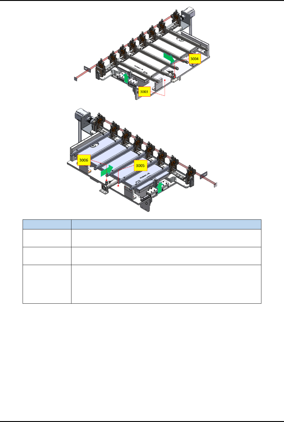
CYL 3004
EXT – Extend the input buffer towards the plasma chamber.
RET – Retract the input buffer from the plasma chamber.
CYL 3006
EXT – Extend the output buffer towards the plasma chamber.
RET – Retract the output buffer from the plasma chamber.
CYL 3003 and
3005
UP – After CYL 3004 and 3006 have extended, CYL 3003 and 3005
will lift the buffer and chamber rails up to allow transfer of strips.
DOWN – CYL 3003 and 3005 will lower the buffer and chamber rails
after strips have been transferred. CYL 3004 and 3006 are only
allowed to retract after this step.
Figure 4-60 Station 30 – Cylinder Control 2 and 3 Locations
FlexTRAK-OH Material Handling System IOM Manual Material Handler Operation
© 2023 Nordson Corporation 4-41
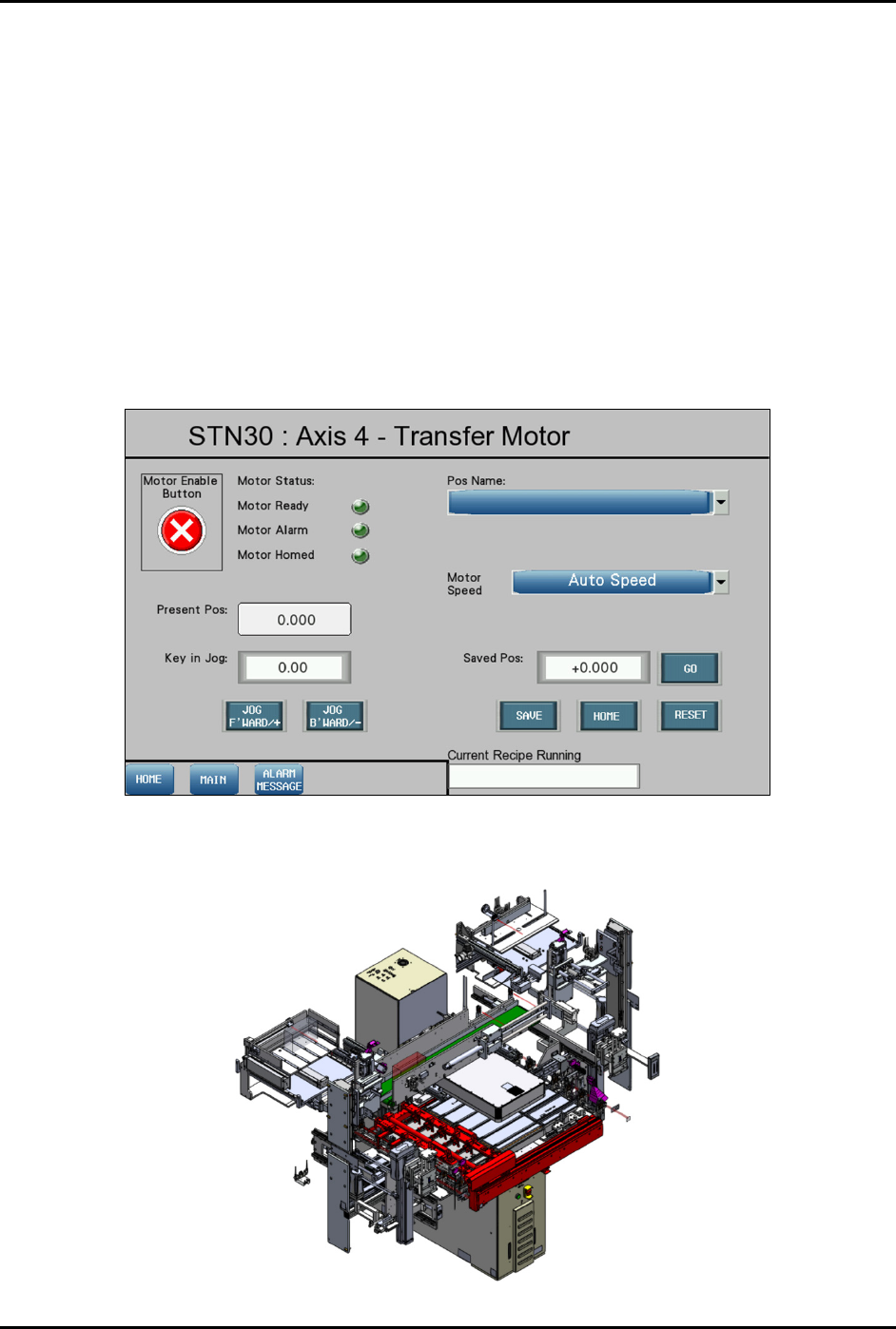
4.12.3.5 Motor Control in Axis 4
Pressing the MOTOR button on the Device Control screen (Figure 4-55) displays a configuration list of
motor driver parameters and the axis platform position.
Refer to 4.11 Station Main Menu Layout for interface descriptions.
The following selections are available in the "Pos Name" drop down list:
• Standby
• Load Position
• Plasma Position
• Unload Position
• Plasma Left Check Position
• Plasma Right Check Position
Figure 4-61 Station 30 – Axis 4 (Transfer Motor) Screen
The red highlighted area in Figure 4-62 shows the location of Axis 4 in Station 30.
Figure 4-62 Station 30 – Axis 4 (Transfer Motor) Location
FlexTRAK-OH Material Handling System IOM Manual Material Handler Operation
4-42 © 2023 Nordson Corporation
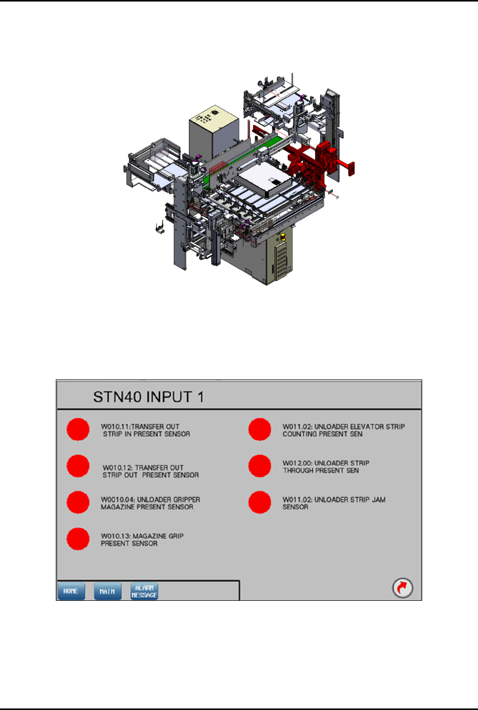
4.12.4 Station 40
The red highlighted area in Figure 4-63 shows the location of Station 40 (transfer output module) in the
FlexTRAK-OH.
Figure 4-63 Station 40 – Transfer Output Module Location
4.12.4.1 Input Screen
Main Screen – Refer to 4.11 Station Main Menu Layout for interface descriptions.
Input Mode – Refer to 4.10 General I/O Screen for interface descriptions.
Figure 4-64 Station 40 – Input 1 Screen