FlexTRAK OH Material Handler Manual.pdf - 第127页
FlexTRAK-OH Material Handli ng System IOM Manual Material Handler Operation © 2023 Nordson C orporation 4-39 4.12.3.4 Cyl inder Control 2 and 3 Figure 4- 58 Station 30 – Cylinde r Control 2 Screen Figure 4- 59 Station 30…
FlexTRAK-OH Material Handling System IOM Manual Material Handler Operation
4-38 © 2023 Nordson Corporation
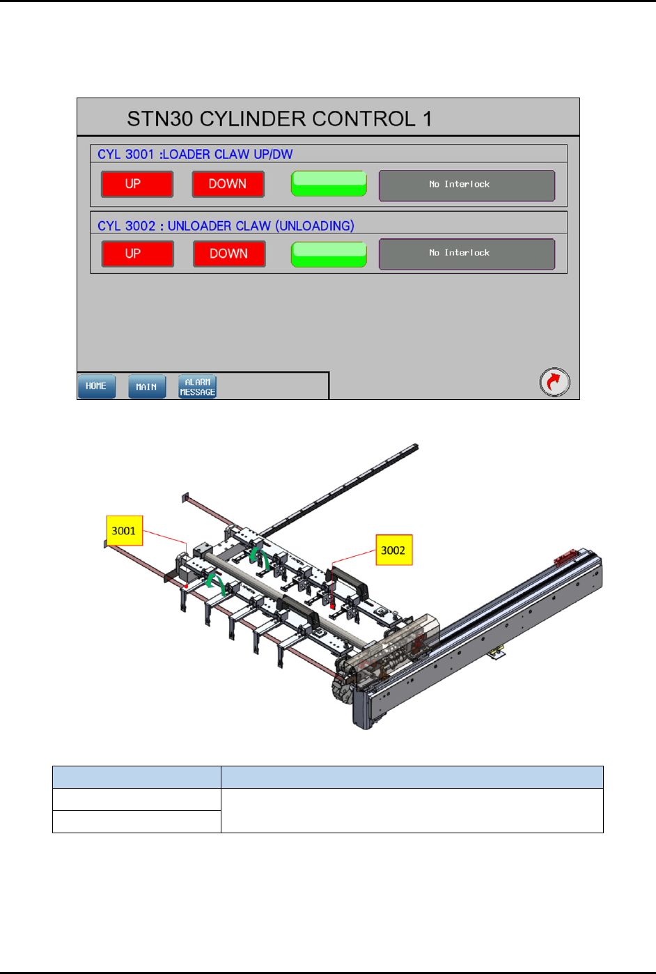
4.12.3.3 Cylinder Control 1
Pressing the CYLINDER button on the Device Control screen (Figure 4-55) will show the control list of
electro-pneumatic cylinders.
Figure 4-56 Station 30 – Cylinder Control 1 Screen
Label
Description
CYL 3001
UP – Ready to move back after transfer the strip.
DOWN – Ready to transfer the strip to another station.
CYL 3002
Figure 4-57 Station 30 – Cylinder Control 1 Location
FlexTRAK-OH Material Handling System IOM Manual Material Handler Operation
© 2023 Nordson Corporation 4-39
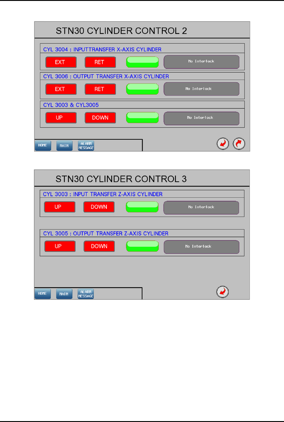
4.12.3.4 Cylinder Control 2 and 3
Figure 4-58 Station 30 – Cylinder Control 2 Screen
Figure 4-59 Station 30 – Cylinder Control 3 Screen
FlexTRAK-OH Material Handling System IOM Manual Material Handler Operation
4-40 © 2023 Nordson Corporation
Label Description
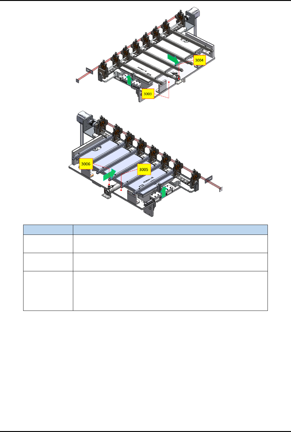
CYL 3004
EXT – Extend the input buffer towards the plasma chamber.
RET – Retract the input buffer from the plasma chamber.
CYL 3006
EXT – Extend the output buffer towards the plasma chamber.
RET – Retract the output buffer from the plasma chamber.
CYL 3003 and
3005
UP – After CYL 3004 and 3006 have extended, CYL 3003 and 3005
will lift the buffer and chamber rails up to allow transfer of strips.
DOWN – CYL 3003 and 3005 will lower the buffer and chamber rails
after strips have been transferred. CYL 3004 and 3006 are only
allowed to retract after this step.
Figure 4-60 Station 30 – Cylinder Control 2 and 3 Locations