FlexTRAK OH Material Handler Manual.pdf - 第18页
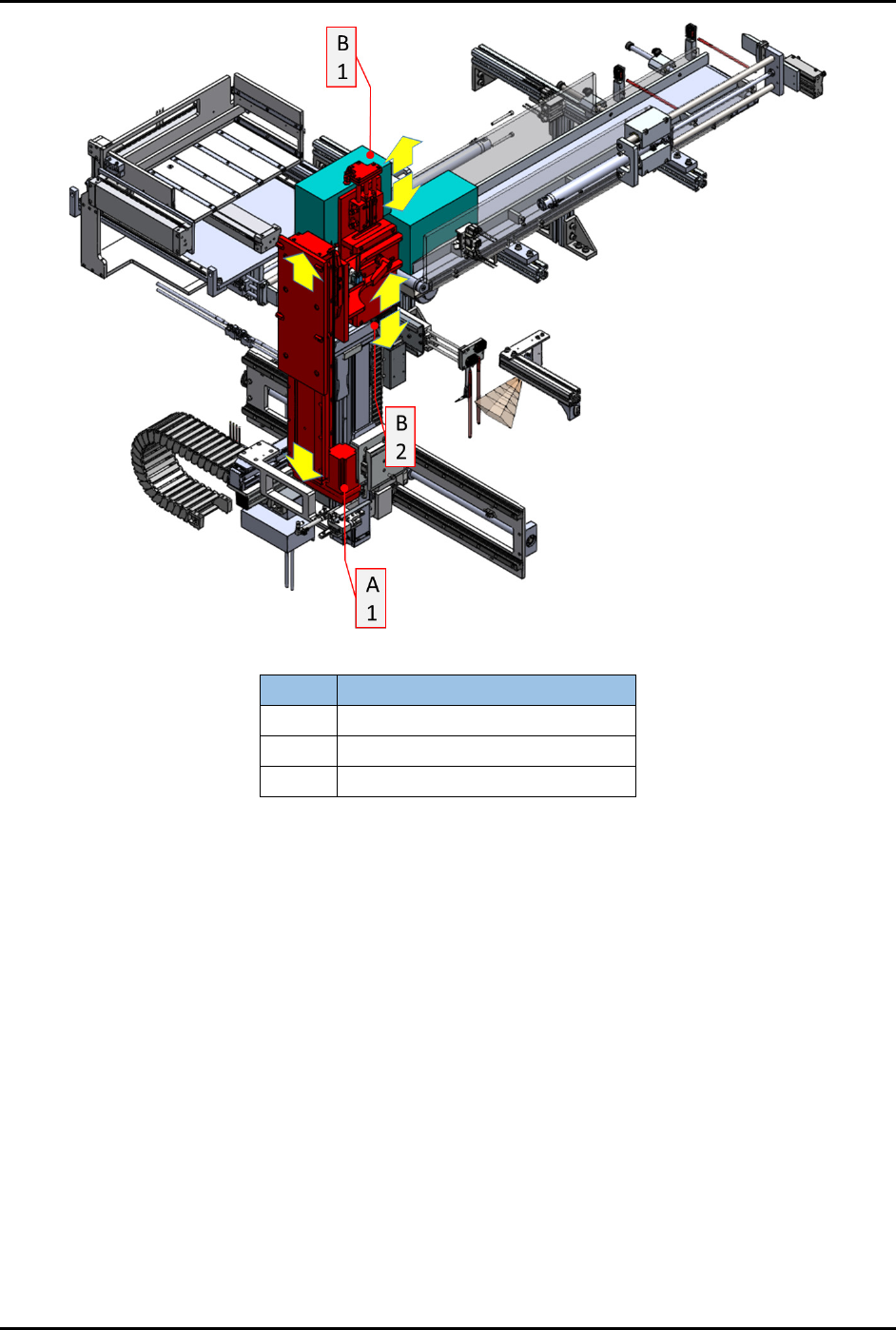
FlexTRAK-OH Material Handli ng System IOM Manual Introductio n 1-8 © 2023 Nordson C orporation Item Name A1 Magazine Elevator M otor B1 Loaded Magazine G ripper B2 Empty Magazine Gripper Figure 1-5 Loader Lift er (Stn20)
FlexTRAK-OH Material Handling System IOM Manual Introduction
© 2023 Nordson Corporation 1-7
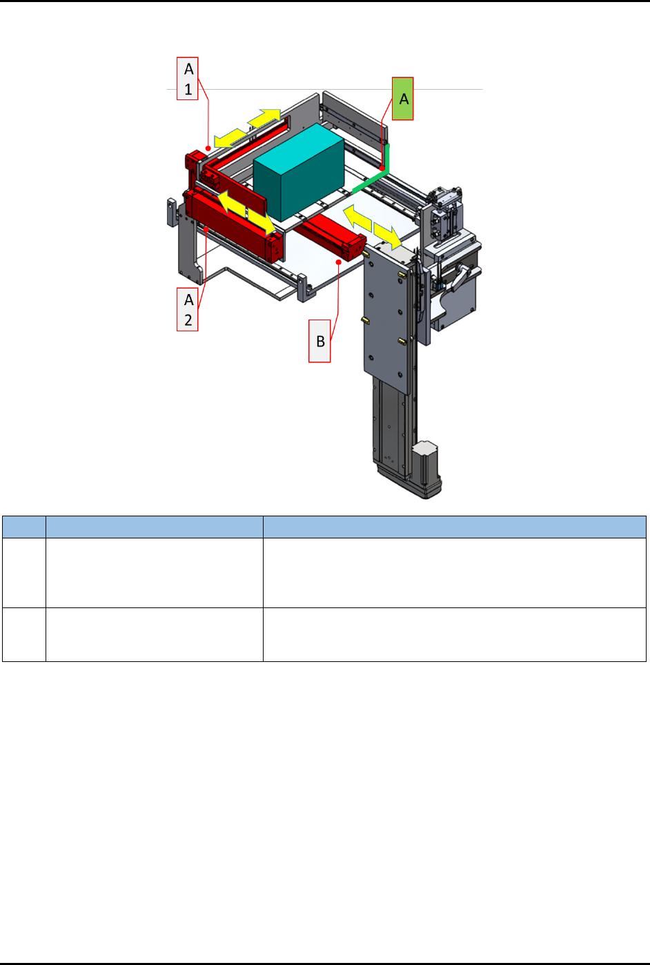
1.5.1 Overhead Magazine Loading Port (Stn10)
Item
Name
Description
A Magazine Precisor Datum Point
The Magazine Precisor Datum Point receives an untreated
strip magazine from the overhead conveyor. The precisor
rear pusher (A1) and precisor side pusher (A2) will push the
magazine to magazine transfer cylinder (B).
B Magazine Transfer Cylinder
The Magazine Transfer Cylinder provides a magazine
bridging to transfer the magazine from this module to loader
lifter module (Figure 1-5).
Figure 1-4 Overhead Magazine Loading Port (Stn10)
1.5.2 Loader Lifter (Stn20)
The Loader Lifter provides a magazine elevator motor (lifting up and down) to transfer the magazine
from loading port module to strip loading buffer and overhead return conveyor modules. Refer to 1.5.3
Strip Loading Buffer (Stn20) for further part descriptions in this module.
FlexTRAK-OH Material Handling System IOM Manual Introduction
1-8 © 2023 Nordson Corporation
Item
Name
A1 Magazine Elevator Motor
B1 Loaded Magazine Gripper
B2 Empty Magazine Gripper
Figure 1-5 Loader Lifter (Stn20)
FlexTRAK-OH Material Handling System IOM Manual Introduction
© 2023 Nordson Corporation 1-9
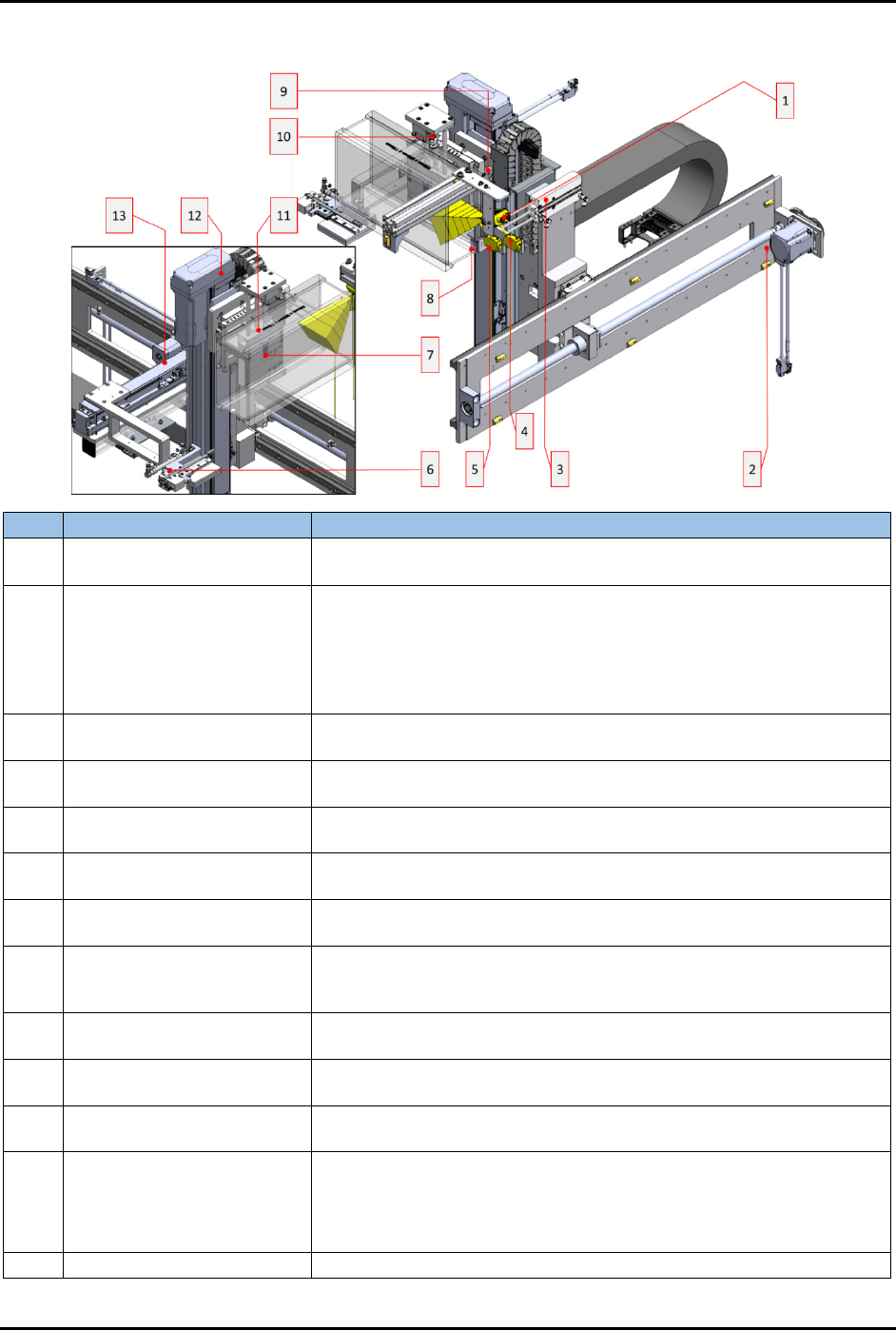
1.5.3 Strip Loading Buffer (Stn20)
Item
Name
Description
1 Strips ID Reader
Reads the strip identification data printed on the surface of the strip,
as shown in Figure 1-14.
2 Axis 1: Y-Axis Actuator
Transfers the Loader Elevator Gripper in the Y-axis to the following
positions:
• Input Magazine Conveyor – magazine loading
• Strip Transfer Buffer Lanes
• Output Magazine Conveyor – magazine unloading
3
Cylinder 2002: Loader
Elevator Pitch Wheel
Positions the Loader Strip In Presence Sensor and the Loader Strip
Out Presence Sensor at the lane location.
4
Loader Strip Out Presence
Sensor
Confirms the kicked strip is presented inside the strip buffering lane.
5
Loader Strip In Presence
Sensor
Confirms the kicked strip is absented at the magazine strip slot.
6
Cylinder 2003: Loader
Elevator Kicker
Pushes the strips out of the magazine slots.
7
Loader Gripper Magazine
Presence Sensor
Ensures the magazine is flush with the gripper rear support plate.
8
Loader Elevator Strip
Counting Presence Sensor
Slot Mapping
Detects the presence of strips in the magazine slots. This feature will
allow the loader elevator kicker to skip the empty slots during the strip
kicking process.
9
Cylinder 2004: Loader
Elevator Zero Gap
Positions the magazine closer to the input buffer lane.
10
Loader Gripper Grip
Presence Sensor
Checks that the magazine is properly gripped.
11
Cylinder 2001: Loader
Elevator Gripper
Actuates the magazine gripper.
12 Axis 2: Z-Axis Actuator
Transfers the clamped magazine in the Z-axis to these positions:
• Input Magazine Conveyor - Magazine Loading
• Strip Transfer Buffer
• Output Magazine Conveyor - Magazine Unloading
13
Axis 10: X-Axis Actuator
Positions the loader elevator kicker to adjust the strip kicking gap.
Figure 1-6 Strip Loading Buffer (Stn20)