FlexTRAK OH Material Handler Manual.pdf - 第56页
FlexTRAK-OH Material Handli ng System IOM Manual Installation 3-6 © 2023 Nordson C orporation 3.7 Setup Procedures Tools and Material s Needed • Strip claw set for claw 1 and claw 2 • Strip lane s et for strip loa ding, …
FlexTRAK-OH Material Handling System IOM Manual Installation
© 2023 Nordson Corporation 3-5
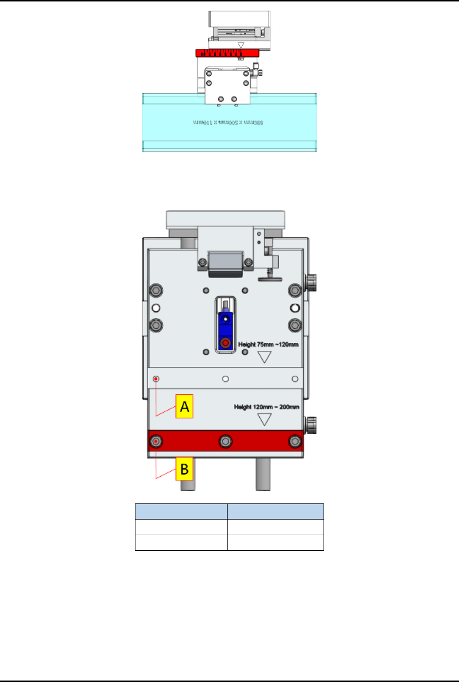
Figure 3-5 Magazine Gripper Scaling Plate
c. The magazine lifter height scaling plate must be configured according to the magazine
height range classification shown in Figure 3-6.
Magazine Height
Use
75 – 120 mm
(A) Top slot
121 – 200 mm
(B) Bottom slot
Figure 3-6 Magazine Lifter Height Scaling Plate
6. Ensure machine is in manual mode. This can be checked from the Home screen of mobile
control pendant (Figure 2-8).
7. Ensure the user access account is logged out.
FlexTRAK-OH Material Handling System IOM Manual Installation
3-6 © 2023 Nordson Corporation
3.7 Setup Procedures
Tools and Materials Needed
• Strip claw set for claw 1 and claw 2
• Strip lane set for strip loading, plasma chamber, and strip unloading
NOTE Each kit part is labeled with the dedicated Kit ID (Kit ID: width x lane quantity). Ensure
the Kit ID assembly groups are correct before proceeding to production or maintenance
mode.
CAUTION! Ensure the machine is in idle mode by verifying that the light tower status light is
solid yellow (Figure 2-12). Ensure all previously handled workpieces (magazine
and strip) are removed from the machine platform.
3.7.1 Conversion Kit Replacement
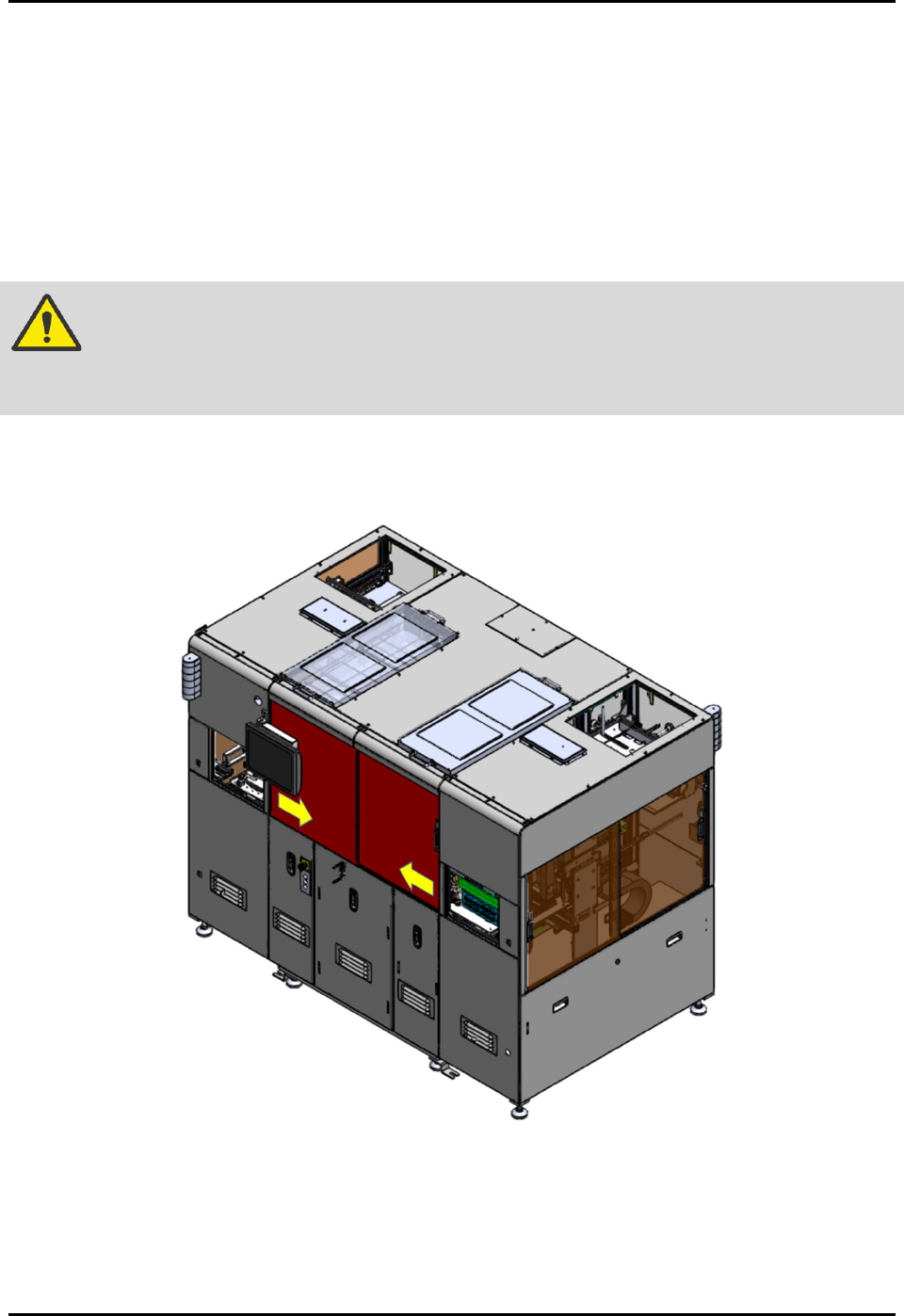
1. Open the front sliding doors to access the machine interior components (Figure 3-7).
Figure 3-7 Open Front Sliding Doors
FlexTRAK-OH Material Handling System IOM Manual Installation
© 2023 Nordson Corporation 3-7
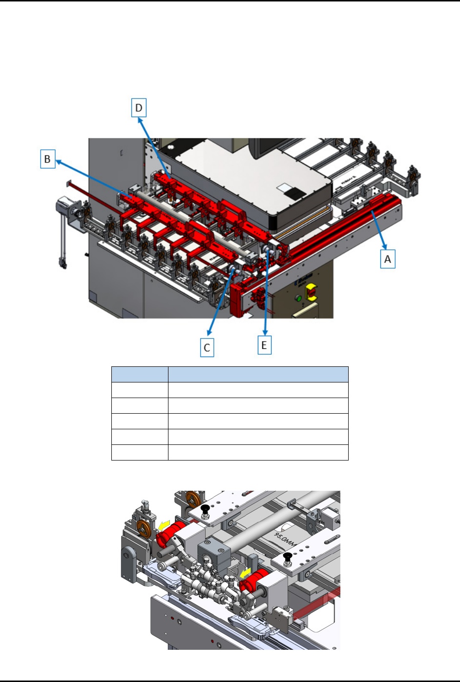
2. Follow the steps below to remove strip claw 1 and strip claw 2. Refer to the item letters in
(Figure 3-8) to perform this procedure.
a. Ensure (A) the claw kit is positioned either at left (loading area) or right side (unloading
area).
b. Safely remove the circular containers (C) and (E) (Figure 3-9).
Item
Name
A X-axis Actuator (transfer motor)
B Strip Claw 1
C Claw 1 Circular Connector
D Strip Claw 2
E Claw 2 Circular Connector
Figure 3-8 Strip Transfer Claw Module Components
Figure 3-9 Remove Circular Connectors