FlexTRAK OH Material Handler Manual.pdf - 第112页
FlexTRAK-OH Material Handli ng System IOM Manual Material Handler Operation 4-24 © 2023 Nordson C orporation 4.12.1.4 Cylinder Control 2 Figure 4- 30 Station 10 – Cylinde r Control 2 Label Description CYL 1004 CLAMP – Cl…
FlexTRAK-OH Material Handling System IOM Manual Material Handler Operation
© 2023 Nordson Corporation 4-23
4.12.1.3 Cylinder Control 1
Pressing the CYLINDER button on the Device Control screen (Figure 4-27) displays the control list of
electro-pneumatic cylinders.
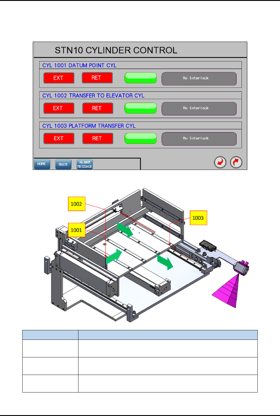
Figure 4-28 Station 10 – Cylinder Control 1
Label
Description
CYL 1001
EXT – Transfer magazine to datum point.
RET – Release magazine pushing.
CYL 1002
EXT – Transfer magazine to elevator gripping base.
RET – Release magazine pushing.
CYL 1003
EXT – Position magazine transfer platform to elevator module.
RET – Position magazine transfer platform to the rear.
Figure 4-29 Station 10 – Cylinder Control 1 Locations
FlexTRAK-OH Material Handling System IOM Manual Material Handler Operation
4-24 © 2023 Nordson Corporation
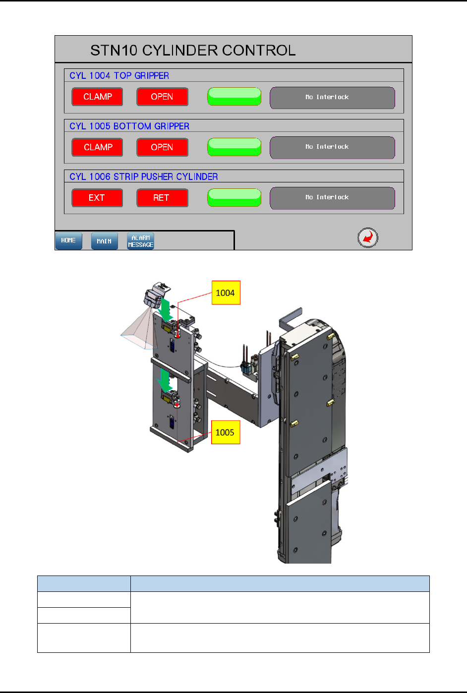
4.12.1.4 Cylinder Control 2
Figure 4-30 Station 10 – Cylinder Control 2
Label
Description
CYL 1004
CLAMP – Clamp magazine.
OPEN – Release magazine.
CYL 1005
CYL 1006
EXT – Push strip against magazine transfer station.
RET – Release strip.
Figure 4-31 Station 10 – Cylinder Control 2 Locations
FlexTRAK-OH Material Handling System IOM Manual Material Handler Operation
© 2023 Nordson Corporation 4-25
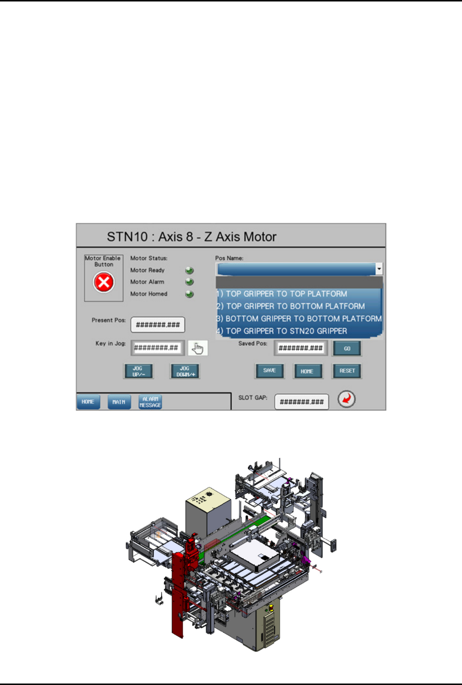
4.12.1.5 Motor Control in Axis 8 (Z-Axis)
Pressing the MOTOR button on the Device Control screen (Figure 4-27) displays a configuration list of
motor driver parameters and the axis platform position.
Refer to 4.11 Station Main Menu Layout for interface descriptions.
The following selections are available in the "Pos Name" drop down list (Figure 4-32):
• Top gripper to top platform
• Top gripper to bottom platform
• Bottom gripper to bottom platform
• Top gripper to Stn20 gripper
• Bottom gripper to Stn20 gripper
• Strip barcode scan position
• Magazine barcode scan position
• Strip slot mapping position
Figure 4-32 Station 10 – Axis 8 (Z-Axis) Screen
The red highlighted area in Figure 4-33 shows the location of Axis 8 in Station 10.
Figure 4-33 Station 10 – Axis 8 (Z-Axis) Location