FlexTRAK OH Material Handler Manual.pdf - 第77页
FlexTRAK-OH Material Handli ng System IOM Manual Installation © 2023 Nordson C orporation 3-27 3.7.6.2 Fine - tuning the Amplifie r 1. Press and hold L/D for 3 t o 5 seconds un til the r ed light is on ( Figure 3- 46 ). …
FlexTRAK-OH Material Handling System IOM Manual Installation
3-26 © 2023 Nordson Corporation
3.7.6 Fine-tuning the Slot Mapping Sensor
The slot mapping sensor and amplifier is assembled in the input elevator module (Station 20).
3.7.6.1 Production Test Flow and Running Concept
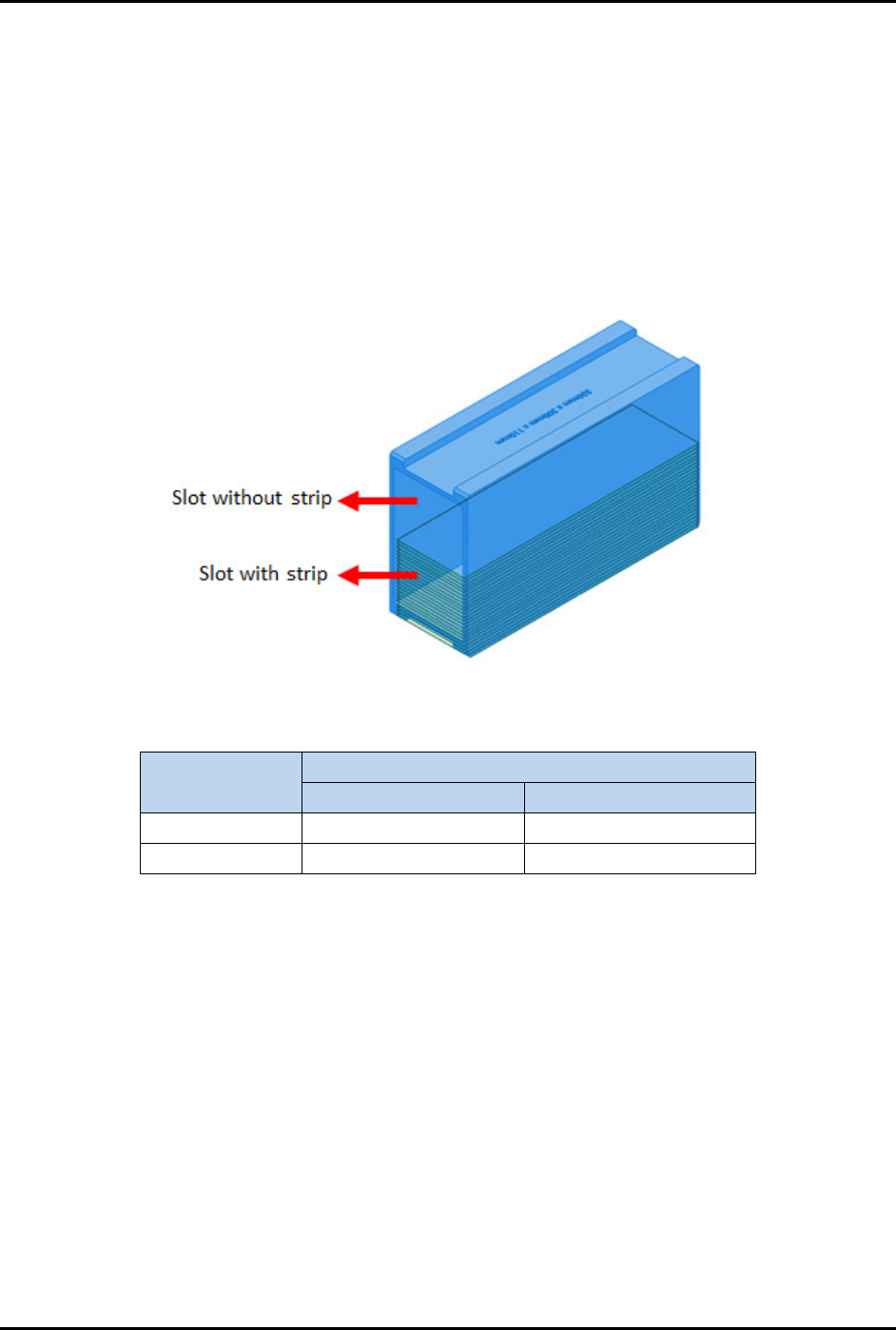
1. Half of the magazine is filled with strips and the other half is empty (Figure 3-45).
2. The strip barcode scanner will scan to see if there is a strip in the magazine slot. If the
magazine slot is empty, the gripper will skip the magazine lifting index during the strip
kicking process.
Example:
Figure 3-45 Magazine Slot With and Without Strip
Table 3-8 Example of Slot Mapping Test
Magazine Slot
Target Threshold Value in Amplifier
Readable
Unreadable
(a) With strip
20
0
(b) Without strip
0
20
• In the magazine slot with a strip (a), the threshold value shown in the amplifier increases
(higher value) when the strip is readable (strip present) and decreases (zero or lower value)
when the strip is unreadable (strip absent).
• In the magazine slot without a strip (b), the threshold value shown in the amplifier increases
(higher value) when strip is unreadable (strip absent) and decreases (zero or lower value)
when strip is readable (strip present).
FlexTRAK-OH Material Handling System IOM Manual Installation
© 2023 Nordson Corporation 3-27
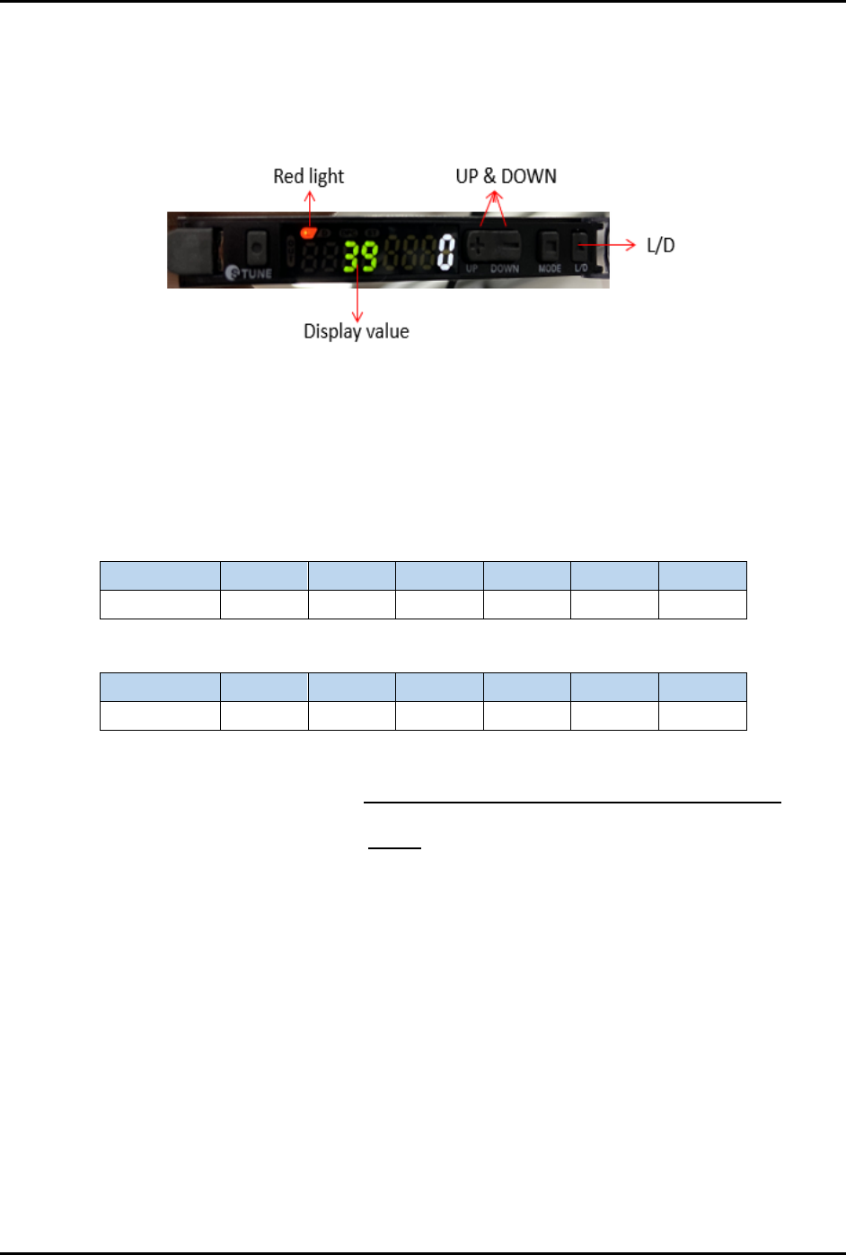
3.7.6.2 Fine-tuning the Amplifier
1. Press and hold L/D for 3 to 5 seconds until the red light is on (Figure 3-46).
2. Press
UP or DOWN to increase or decrease the threshold limit, until the correct threshold
limit is displayed on the screen.
Figure 3-46 Fine-tuning the Amplifier
3.7.6.3 Setting the Amplifier Threshold Limit
The threshold limit decreases (zero or lower value) when the magazine contains a strip and increases
(higher value) when there is no strip in the magazine. Table 3-9 and Table 3-10 show sample readings
obtained in these two modes.
Table 3-9 Without Strip Result
Sensor IO
Slot 1
Slot 2
Slot 3
Slot 4
Slot 5
Slot 6
I005.02 110 140 130 84 90 170
Table 3-10 With Strip Result
Sensor IO
Slot 1
Slot 2
Slot 3
Slot 4
Slot 5
Slot 6
I005.02 0 0 0 2 0 0
Threshold limit set in amplifier =
(lowest value without strip + highest value with strip)
2
=
(84+2)
2
= 43
Perform Step 2 in 3.7.6.2 Fine-tuning the Amplifier and press the UP or DOWN button to adjust the
threshold limit until "43" is displayed on the screen.
FlexTRAK-OH Material Handling System IOM Manual Installation
3-28 © 2023 Nordson Corporation
3.7.7 Pinch Wheel Setup
3.7.7.1 Pinch Wheel End Block Installation and/or Removal
The pinch wheel end block (Figure 3-47) must be installed at end of the rail (machine front side) for both
input and output buffer lanes. The purpose is to guide the position of the pinch wheel on the LM (linear
motion) rail between first lane and last lane.
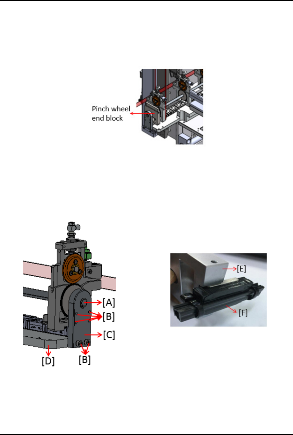
Figure 3-47 Pinch Wheel End Block
To install the pinch wheel end block on LM rail:
1. Remove circlip (A).
2. Loosen all screws (B) and remove the shaft stopper block (C) from pinch wheel plate (D).
3. Insert the pinch wheel end block (E) into LM guide rail (F).
Figure 3-48 Installing the Pinch Wheel