FlexTRAK OH Material Handler Manual.pdf - 第62页
FlexTRAK-OH Material Handli ng System IOM Manual Installation 3-12 © 2023 Nordson C orporation Figure 3- 21 Remove Base A ssembly from Chambe r Area c. P lace a correct ch amber conver sion kit for new pro duction rec ip…
FlexTRAK-OH Material Handling System IOM Manual Installation
© 2023 Nordson Corporation 3-11
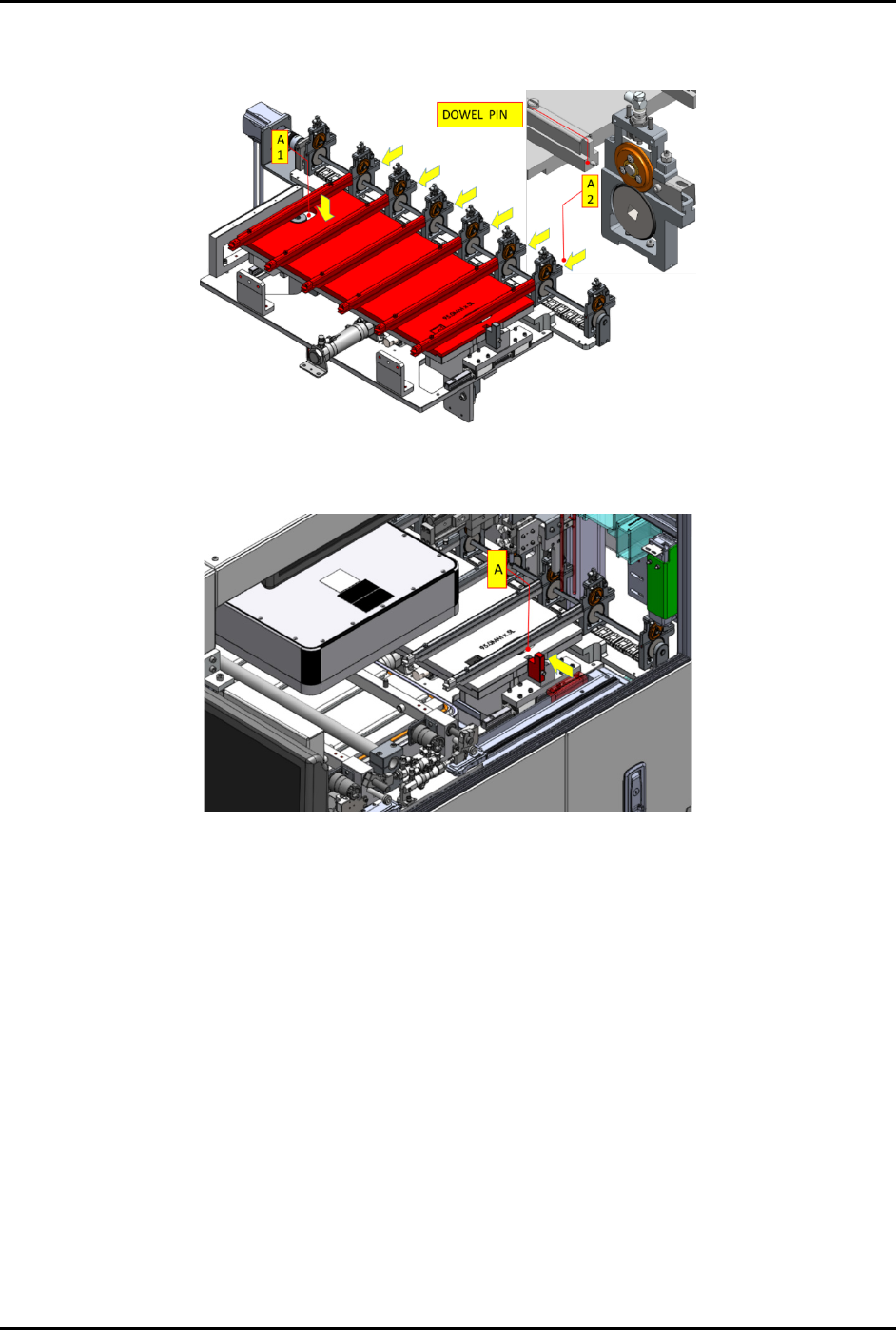
d. Place the correct conversion kit for new production recipe (A1). Install the pinch wheel
assembly with the dowel pins on unloading lane (A2) (Figure 3-19).
Figure 3-19 Place Correct Unloading Lane to Machine
e. Push (A) in the direction indicated by the yellow arrow to lock the conversion kit.
Figure 3-20 Lock Conversion Kit in Place
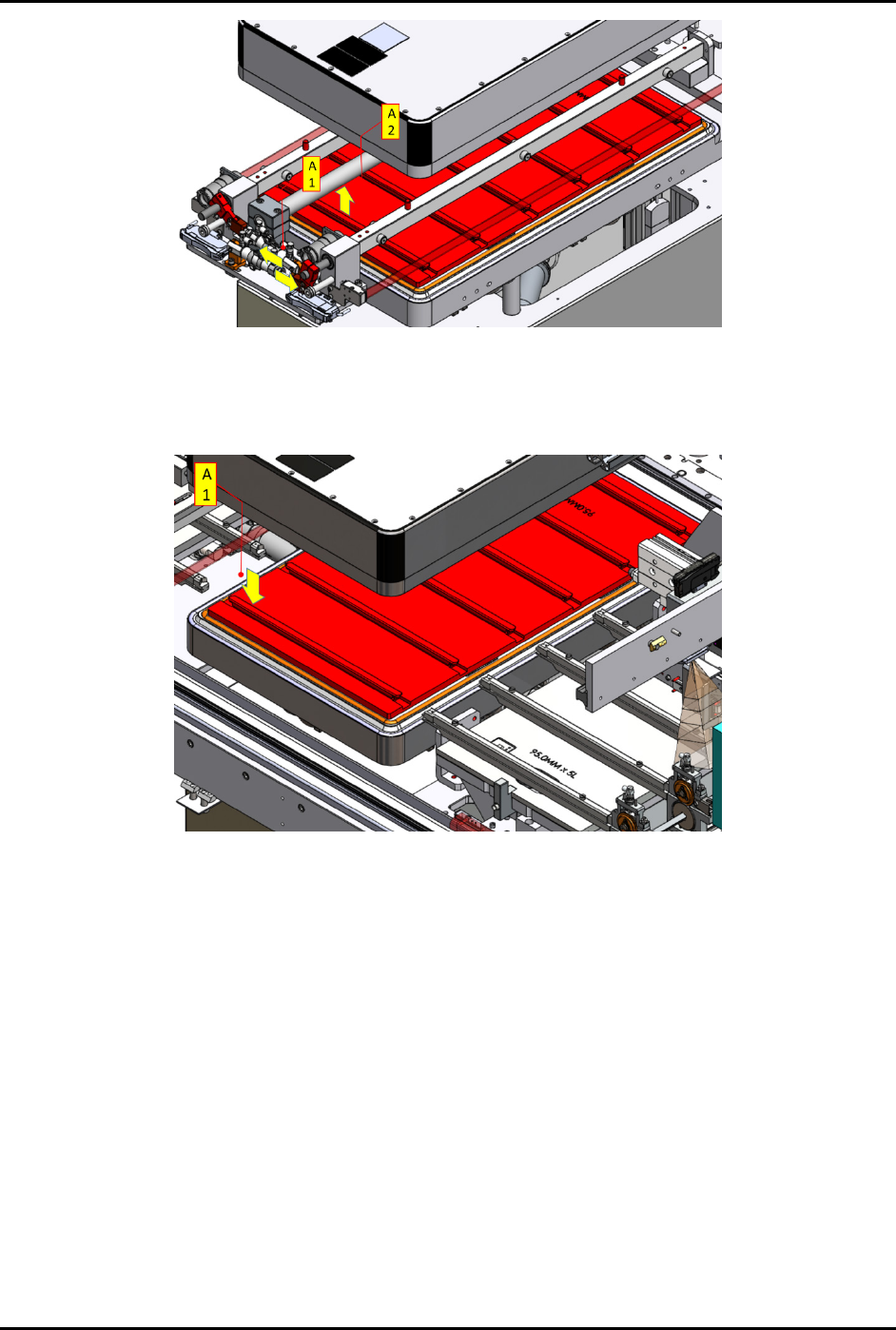
6. Follow the steps below to remove and assemble the chamber conversion kit at the plasma
chamber station:
a. Push out the strip transfer claw – base assembly from the chamber area (A1)
(Figure 3-21).
b. Manually lift the kit up (A2) and remove from the machine. Safely place the kit on a
conversion keeping rack.
FlexTRAK-OH Material Handling System IOM Manual Installation
3-12 © 2023 Nordson Corporation
Figure 3-21 Remove Base Assembly from Chamber Area
c. Place a correct chamber conversion kit for new production recipe (A1) (Figure 3-22).
d. Ensure all the rails sit properly inside the pocket of the base plate.
Figure 3-22 Installing Chamber Kit in Plasma Chamber
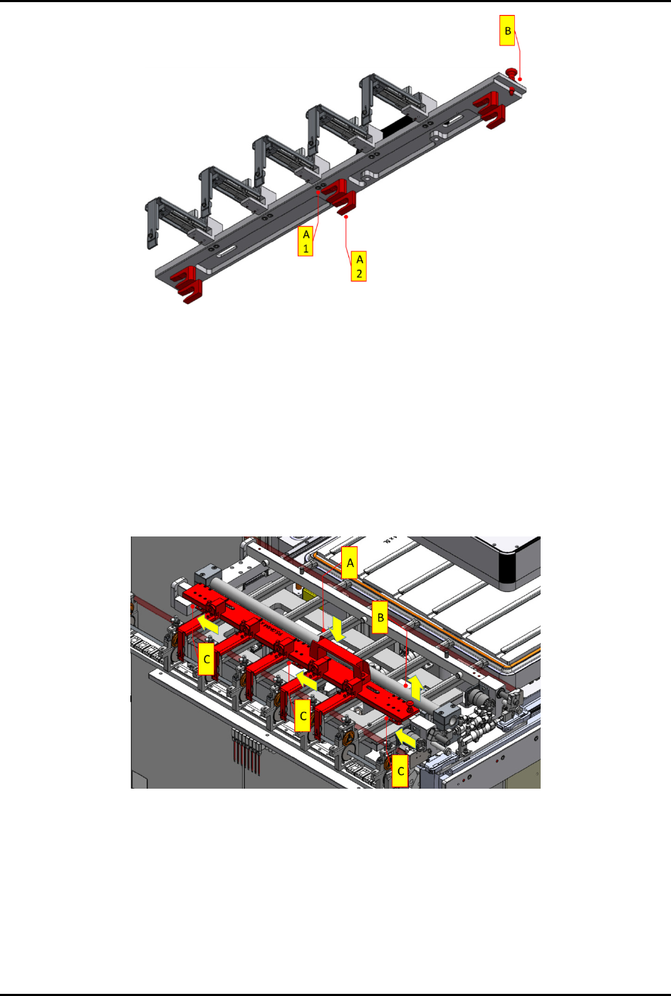
7. Follow the steps below to assemble strip claw 1 and strip claw 2:
a. Place a correct strip claw 1 assembly for new production setup.
b. Ensure the components on the claw module are properly assembled (Figure 3-23).
• CAM follower guides (A1) and (A2)
• Locking plunger (B)
FlexTRAK-OH Material Handling System IOM Manual Installation
© 2023 Nordson Corporation 3-13
Figure 3-23 Claw Module Components
c. Ensure all sensor cables, connection sockets, air tubes, and the vacuum manifold are in
good condition.
All fingers on the claw module should be able to move freely.
d. Install strip claw 1 assembly onto the strip transfer claw module – claw 1 linkage
(Figure 3-24).
e. Holding the handle (A), pull up and hold locking plunger (B). Then push forward the
claw (C) via the handle guided by the CAM follower guides.
The CAM follower guides are labeled A1 and A2 (Figure 3-23).
Figure 3-24 Installation of Strip Claw 1