FlexTRAK OH Material Handler Manual.pdf - 第72页
FlexTRAK-OH Material Handli ng System IOM Manual Installation 3-22 © 2023 Nordson C orporation 3.7.5 Fine - tuning the Str ip Sensor s 3.7.5.1 LR - ZB250 S eries Figure 3- 43 shows the c omponents name in LR - ZB250 se n…
FlexTRAK-OH Material Handling System IOM Manual Installation
© 2023 Nordson Corporation 3-21
3.7.4 Strip Jam Sensor Installation and/or Adjustment
Table 3-1 Strip Sensors in FlexTRAK-SHS
Sensor IO
Sensor Model
Sensor Position
I004.12 LR-ZB250
Refer to items 4 and 5 in Strip Loading Buffer station. See
1.5.3 Strip Loading Buffer (Stn20)
I004.13 LR-ZB250
I010.11 LR-ZB250
Refer to items 6 and 7 in Strip Unloading Buffer station.
See 1.5.8 Strip Unloading Buffer (Stn40)
I010.12 LR-ZH500
Table 3-2 General Comparison Between LR-ZB250 and LR-ZH500 Sensors
Item
LR-ZB250
LR-ZH500
Detectable distance (distance between sensor and strip) 35-200 mm 35-500 mm
Red spot size on strip Smaller Bigger
Reading color Red White
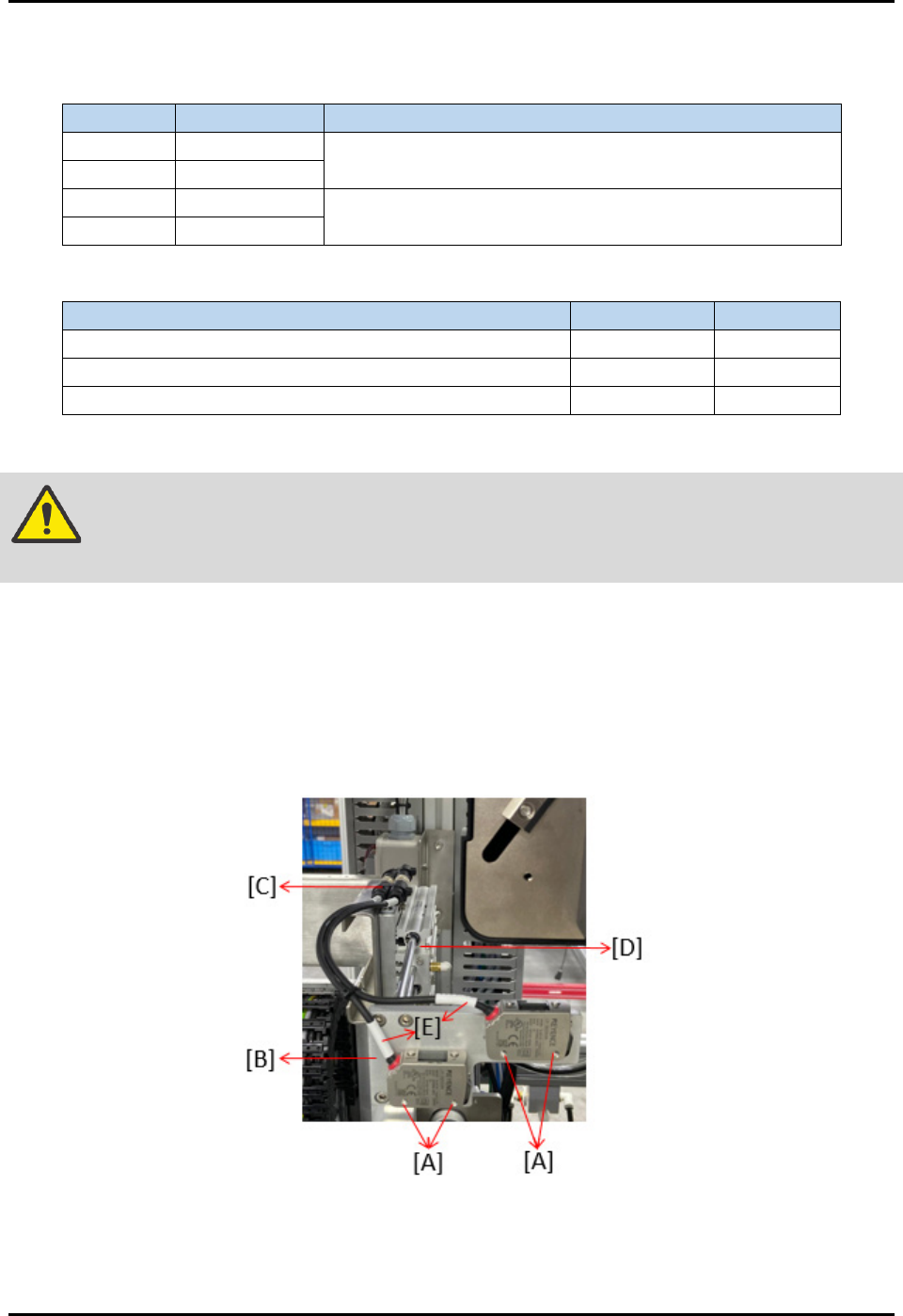
To install or adjust the buffer station strip sensor (Figure 3-42):
WARNING! Before removing, marking the position of screw to prevent machine misaligned
during sensor replacement.
1. Remove four screws (A) to loosen sensor from the rear support plate (B).
2. Remove two connectors (C) that connected sensors with the loader elevator pinch wheel (D).
3. Remove sensor wiring cables (E), then take out the whole sensor from the slot.
4. Reverse all the above steps to assemble a new sensor. Beware on the mounting distance
between sensor and strip lane, as stated in Table 3-2.
Figure 3-42 Strip Jam Sensor Installation and/or Adjustment
NOTE This setting is applicable for strip sensors located in both loader and unloader buffer
lanes. See 3.7.5 Fine-tuning the Strip Sensors.
FlexTRAK-OH Material Handling System IOM Manual Installation
3-22 © 2023 Nordson Corporation
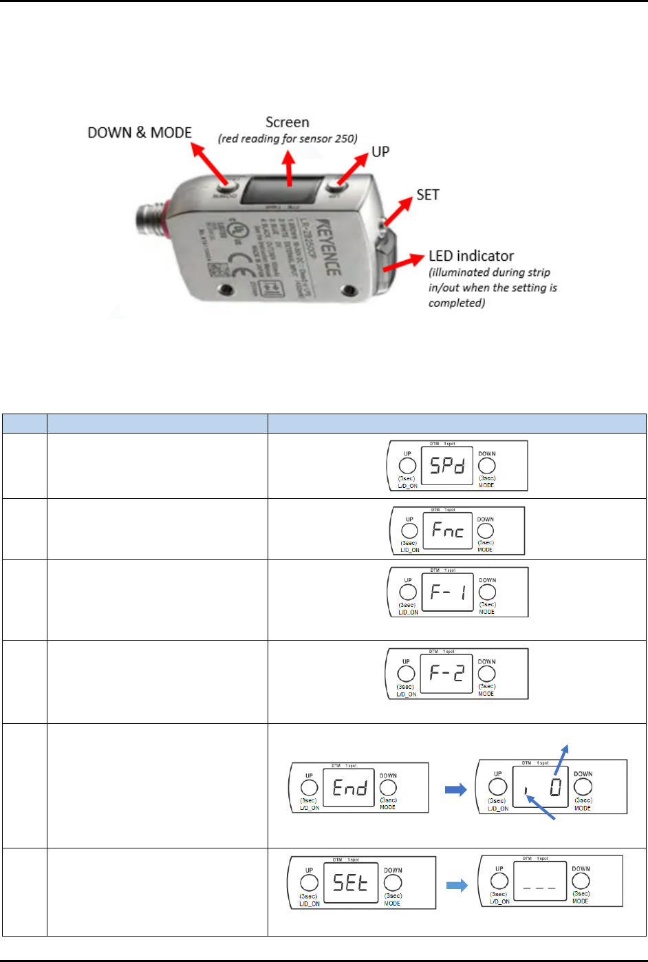
3.7.5 Fine-tuning the Strip Sensors
3.7.5.1 LR-ZB250 Series
Figure 3-43 shows the components name in LR-ZB250 sensor:
Figure 3-43 LR-ZB250 Series Strip Sensor
Table 3-3 explains how to fine-tune the LR-ZB250 sensor:
Table 3-3 Steps to Fine-tune LR-ZB250 Sensor
Step
Action
Display on screen
1
Long press MODE button for 3 to
5 seconds.
2
Simultaneously, press once on
both UP and DOWN buttons.
3 Press once on UP button.
*** blinking ***
4 Press once on UP button.
*** blinking ***
5
Long press MODE button for 3 to
5 seconds.
6 Press once on SET button.
Stands for i-Datum
Original value
*** blinking ***
FlexTRAK-OH Material Handling System IOM Manual Installation
© 2023 Nordson Corporation 3-23
Step
Action
Display on screen
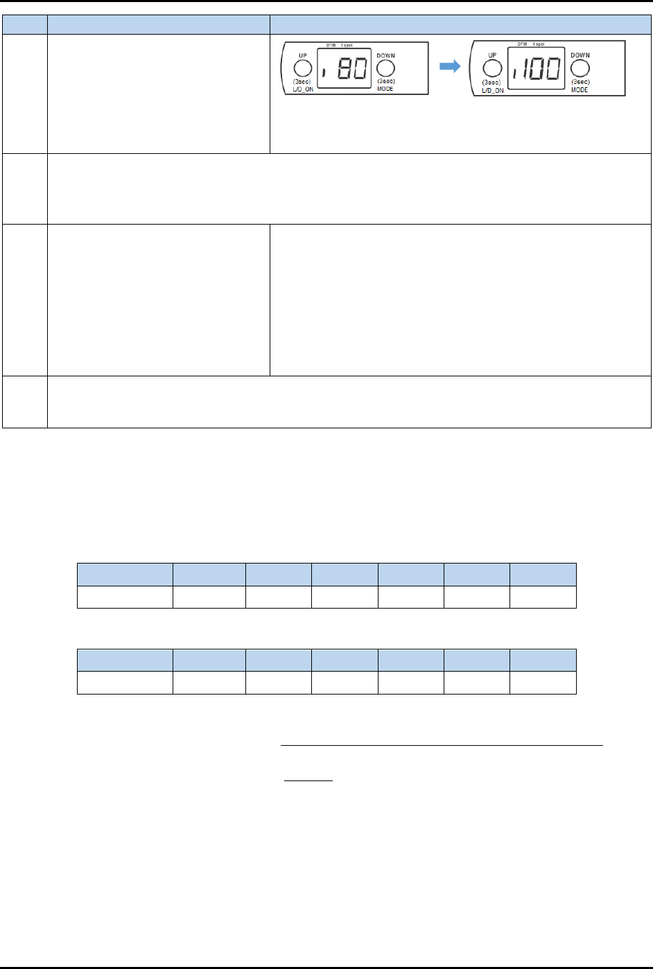
7
Long press SET button for 3 to 5
seconds.
Note: Ensure no strip present or
common background while doing
this step.
80 = Current threshold limit
Displays any value, and blinking. Example:
100 = actual optimum reading (without strip)
8
Step 6 and Step 7 above are for i-datum settings, after the small "i" has appeared on the screen
in step 5. When all settings are done, "DTM" and "1 spot" indicators will light up in Step 7.
DTM (orange light) stands for datum
1 spot (green light) stands for sensor stability
9
Press UP or DOWN button to
adjust the value.
If set value > display value in Step 7, press UP
If set value < display value in Step 7, press DOWN
After adjusting the value, the new value will blink and
immediately change on screen. It will be autosaved after a
while.
The LED indicator at the side will illuminate, which means
the signal is successfully detected in the machine.
See 3.7.5.2 How to Set Threshold Limit in Strip Sensor
for
further details.
10
Add off delay in sensor. The purpose of this setting is to prevent a false alarm signal from a
reflective die telling the system that the strip is absent. See 3.7.5.3 Delay Timer Settings for
further details.
3.7.5.2 How to Set Threshold Limit in Strip Sensor
The threshold limit decreases (zero or lower value) when the platform contains a strip and increases
(higher value) when there is no strip. Table 3-4 and Table 3-5 show the sample readings obtained in these
two modes.
Table 3-4 Sensor Reading Without Strip
Sensor No. Lane 1 Lane 2 Lane 3 Lane 4 Lane 5 Lane 6
1 100 90 96 84 80 90
Table 3-5 Sensor Reading With Strip
Sensor No. Lane 1 Lane 2 Lane 3 Lane 4 Lane 5 Lane 6
1 7 0 36 1 0 5
Threshold limit set in strip sensor =
(lowest value without strip + highest value with strip)
2
=
(80+36)
2
= 58
Follow Step 8 in Table 3-3 and press the UP or DOWN button on LR-ZB250 sensor to adjust the value
until "58" is displayed on the screen.