FlexTRAK OH Material Handler Manual.pdf - 第71页
FlexTRAK-OH Material Handli ng System IOM Manual Installation © 2023 Nordson C orporation 3-21 3.7.4 Strip Jam Sensor I nstallatio n and/or Adj ustment Table 3-1 Strip Sensors in FlexTRAK - SH S Sensor IO Sensor Model Se…
FlexTRAK-OH Material Handling System IOM Manual Installation
3-20 © 2023 Nordson Corporation
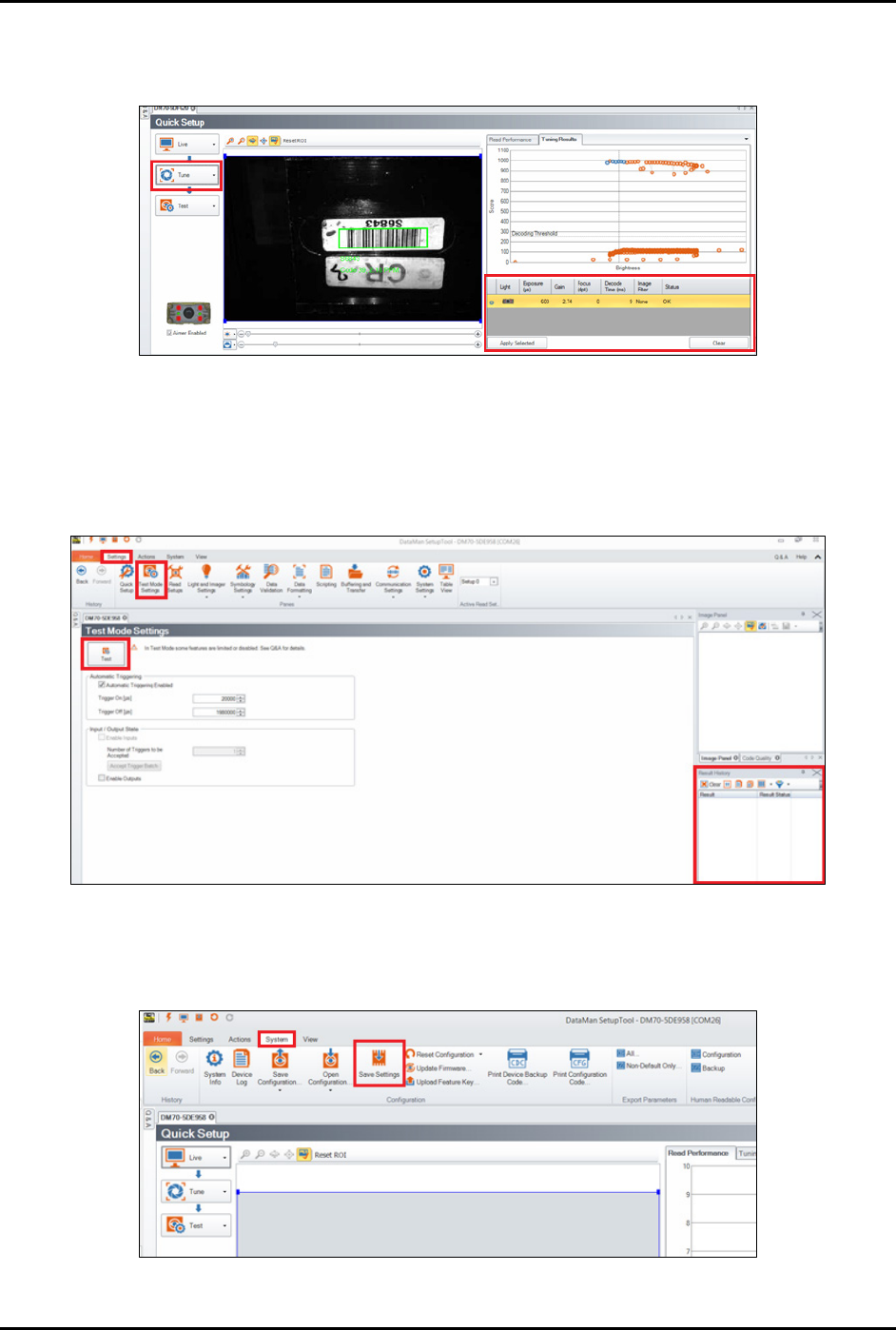
c. Select Tune.
The system will autotune the brightness in order to get an optimum tuning result.
Figure 3-39 Autotune the Brightness
6. Select System > Test Mode Settings to test the setting result (Figure 3-40).
7. Click
Test on the left panel.
The result status will display on Result History window on bottom right panel.
Figure 3-40 DataMan Software – Test and Result History
8. When done, select System > Save Settings to save the current settings to the scanner
(Figure 3-41).
Figure 3-41 DataMan Software - Save Settings
FlexTRAK-OH Material Handling System IOM Manual Installation
© 2023 Nordson Corporation 3-21
3.7.4 Strip Jam Sensor Installation and/or Adjustment
Table 3-1 Strip Sensors in FlexTRAK-SHS
Sensor IO
Sensor Model
Sensor Position
I004.12 LR-ZB250
Refer to items 4 and 5 in Strip Loading Buffer station. See
1.5.3 Strip Loading Buffer (Stn20)
I004.13 LR-ZB250
I010.11 LR-ZB250
Refer to items 6 and 7 in Strip Unloading Buffer station.
See 1.5.8 Strip Unloading Buffer (Stn40)
I010.12 LR-ZH500
Table 3-2 General Comparison Between LR-ZB250 and LR-ZH500 Sensors
Item
LR-ZB250
LR-ZH500
Detectable distance (distance between sensor and strip) 35-200 mm 35-500 mm
Red spot size on strip Smaller Bigger
Reading color Red White
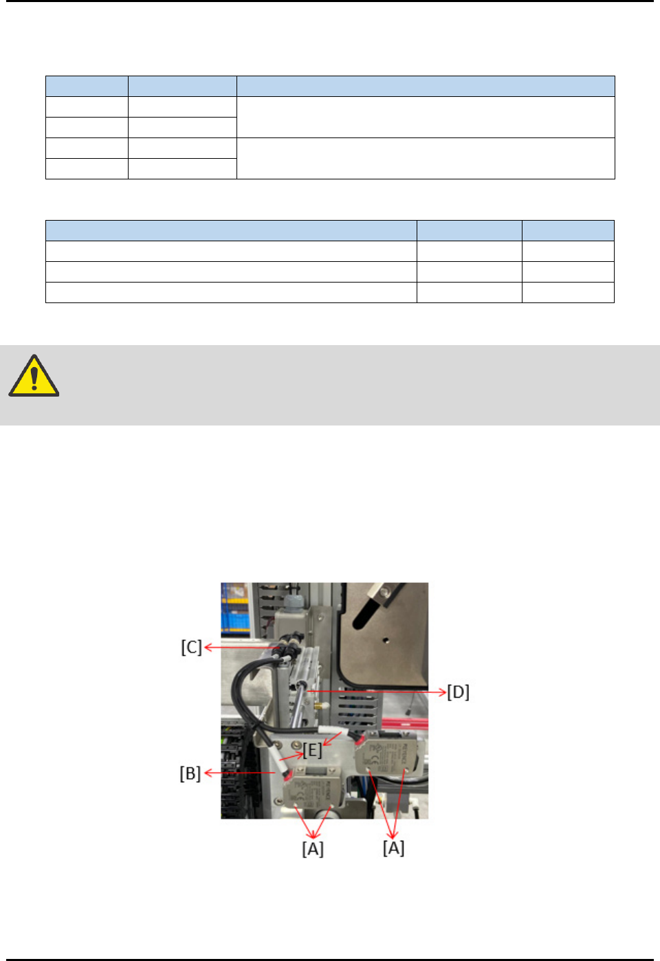
To install or adjust the buffer station strip sensor (Figure 3-42):
WARNING! Before removing, marking the position of screw to prevent machine misaligned
during sensor replacement.
1. Remove four screws (A) to loosen sensor from the rear support plate (B).
2. Remove two connectors (C) that connected sensors with the loader elevator pinch wheel (D).
3. Remove sensor wiring cables (E), then take out the whole sensor from the slot.
4. Reverse all the above steps to assemble a new sensor. Beware on the mounting distance
between sensor and strip lane, as stated in Table 3-2.
Figure 3-42 Strip Jam Sensor Installation and/or Adjustment
NOTE This setting is applicable for strip sensors located in both loader and unloader buffer
lanes. See 3.7.5 Fine-tuning the Strip Sensors.
FlexTRAK-OH Material Handling System IOM Manual Installation
3-22 © 2023 Nordson Corporation
3.7.5 Fine-tuning the Strip Sensors
3.7.5.1 LR-ZB250 Series
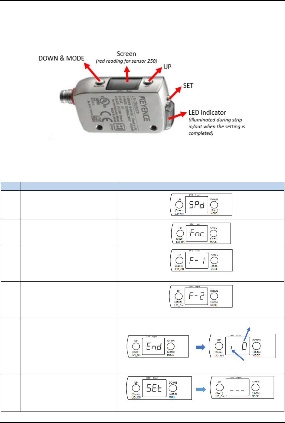
Figure 3-43 shows the components name in LR-ZB250 sensor:
Figure 3-43 LR-ZB250 Series Strip Sensor
Table 3-3 explains how to fine-tune the LR-ZB250 sensor:
Table 3-3 Steps to Fine-tune LR-ZB250 Sensor
Step
Action
Display on screen
1
Long press MODE button for 3 to
5 seconds.
2
Simultaneously, press once on
both UP and DOWN buttons.
3 Press once on UP button.
*** blinking ***
4 Press once on UP button.
*** blinking ***
5
Long press MODE button for 3 to
5 seconds.
6 Press once on SET button.
Stands for i-Datum
Original value
*** blinking ***