FlexTRAK OH Material Handler Manual.pdf - 第159页
FlexTRAK-OH Material Handli ng System IOM Manual Material Handler Operation © 2023 Nordson C orporation 4-71 c. Ent er the tag ID ob tained from Table 4-6 into Recipe# screen Where : 74 = strip size 006 = lane qua ntity …
FlexTRAK-OH Material Handling System IOM Manual Material Handler Operation
4-70 © 2023 Nordson Corporation
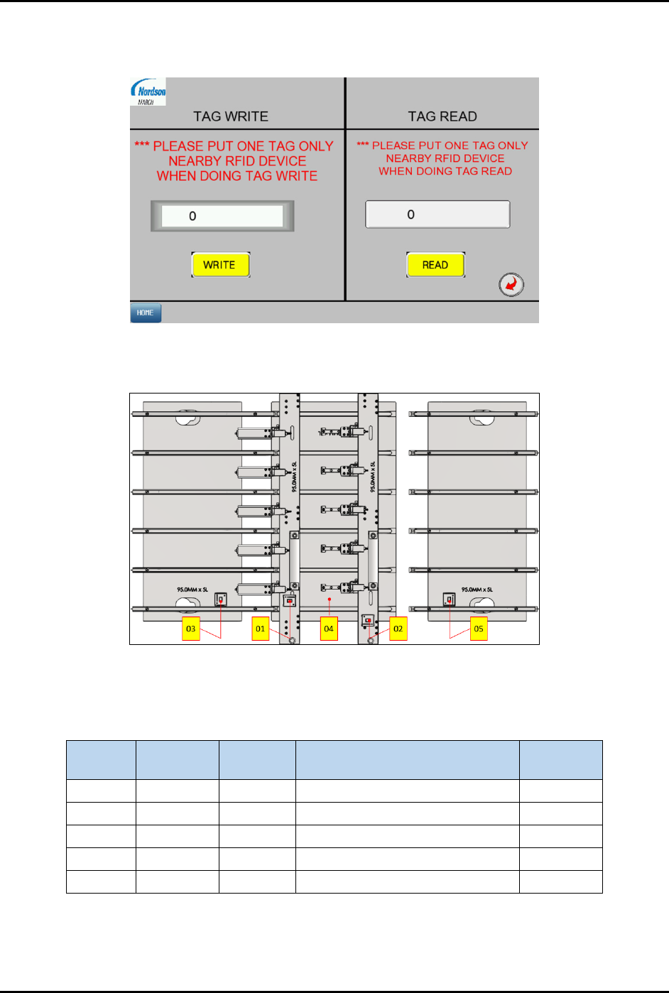
4. Enter the dedicated RFID tag parts ID into the screen (Figure 4-116).
The following steps explain how to determine the tag ID.
Figure 4-116 RFID Tab – Screen 2
a. Identify the RFID location in the strip lane kit module (Figure 4-117).
Figure 4-117 Identify the RFID Location
b. The RFID Tag ID labeling convention is shown in Table 4-6.
Table 4-6 RFID Labeling Convention
Tag No.
Strip Size
(mm)
Lane
Quantity
Strip Lane Kit Module Tag ID
TAG 1 74.00 6 01 – Loader Claw 7400601
TAG 2
74.00
6
02 – Unloader Claw
7400602
TAG 3 74.00 6 03 – Loader Input Buffer Plate 7400603
TAG 4 74.00 6 04 – Plasma Buffer Plate 7400604
TAG 5 74.00 6 05 – Unloader Input Buffer Plate 7400605

FlexTRAK-OH Material Handling System IOM Manual Material Handler Operation
© 2023 Nordson Corporation 4-71
c. Enter the tag ID obtained from Table 4-6 into Recipe# screen
Where:
74 = strip size
006 = lane quantity
01 to 05 = RFID location labeling in strip lane kit module
Note: Tag ID will be varied when the strip size and lane quantity used is different.
5. Hold the dedicated RFID tag parts close to the RFID device.
6. Press WRITE to execute the RFID device writing process, and press READ to execute the
RFID device reading process (Figure 4-116).
Ensure the Tag Write and Tag Read fields show the correct tag ID as declared or
written.
7. Insert the RFID parts into the designated location in the RFID holding fixture.
8. Repeat Step 4 through Step 7 until all RFID parts are completely written and read.
9. When all settings are done, press HOME on bottom left corner to return into home screen.
4.18 Barcode/2D Reader Setup
4.18.1 Magazine
Refer 3.7.3 Magazine Scanner Installation and/or Adjustment (Optional Feature) for similar descriptions.
4.18.2 Strip
The Strip ID as shown in Figure 1-14 is readable with strip ID reader Refer to 1.5.3 Strip Loading Buffer
(Stn20).
To configure the software for the Strip ID reader:
1. Connect the laptop to the machine via LAN cable.
2. Close "Microscan AutoVision software".
3. Open "Visionscape" software.
4. On top right corner of the Visionscape FrontRunner window, click
Add Btn to add the
camera device.
FlexTRAK-OH Material Handling System IOM Manual Material Handler Operation
4-72 © 2023 Nordson Corporation
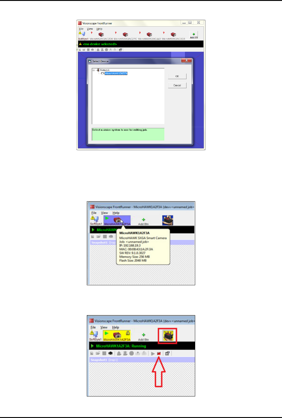
5. Select the vision system and click OK to proceed to the next step (Figure 4-118).
Figure 4-118 Visionscape FrontRunner – Select Vision System
6. Select the camera according to the IP address (Figure 4-119).
• 192.168.19.3 – Loader strip scanner
• 192.168.19.4 – Unloader strip scanner
Figure 4-119 Select Camera According to IP Address
7. When the camera selection field turns yellow, select Stop Running Camera (Figure 4-120).
Figure 4-120 Select Stop Running Camera